00198706-01_AI_Stationaere_Kamera_25_33_GigE_SXV3_DE_EN.pdf - 第80页
3 Installation 3.8 Final work 80 Assembly Instructions / Montageanleitung SIPLACE SX1/SX2 V3 Stationäre Kamera Typ 25/33 (GigE) Stationary Camera Type 25/33 (GigE) 03/2021 Fig.29: Configuration ► Configure the installed…
3 Installation
3.8 Final work
Assembly Instructions / Montageanleitung SIPLACE SX1/SX2 V3 Stationäre Kamera Typ 25/33 (GigE) Stationary
Camera Type 25/33 (GigE) 03/2021
79
3.8 Final work
► Hook in the housing for the lower section of the camera. This is either screwed or hooked into
place, depending on your camera type.
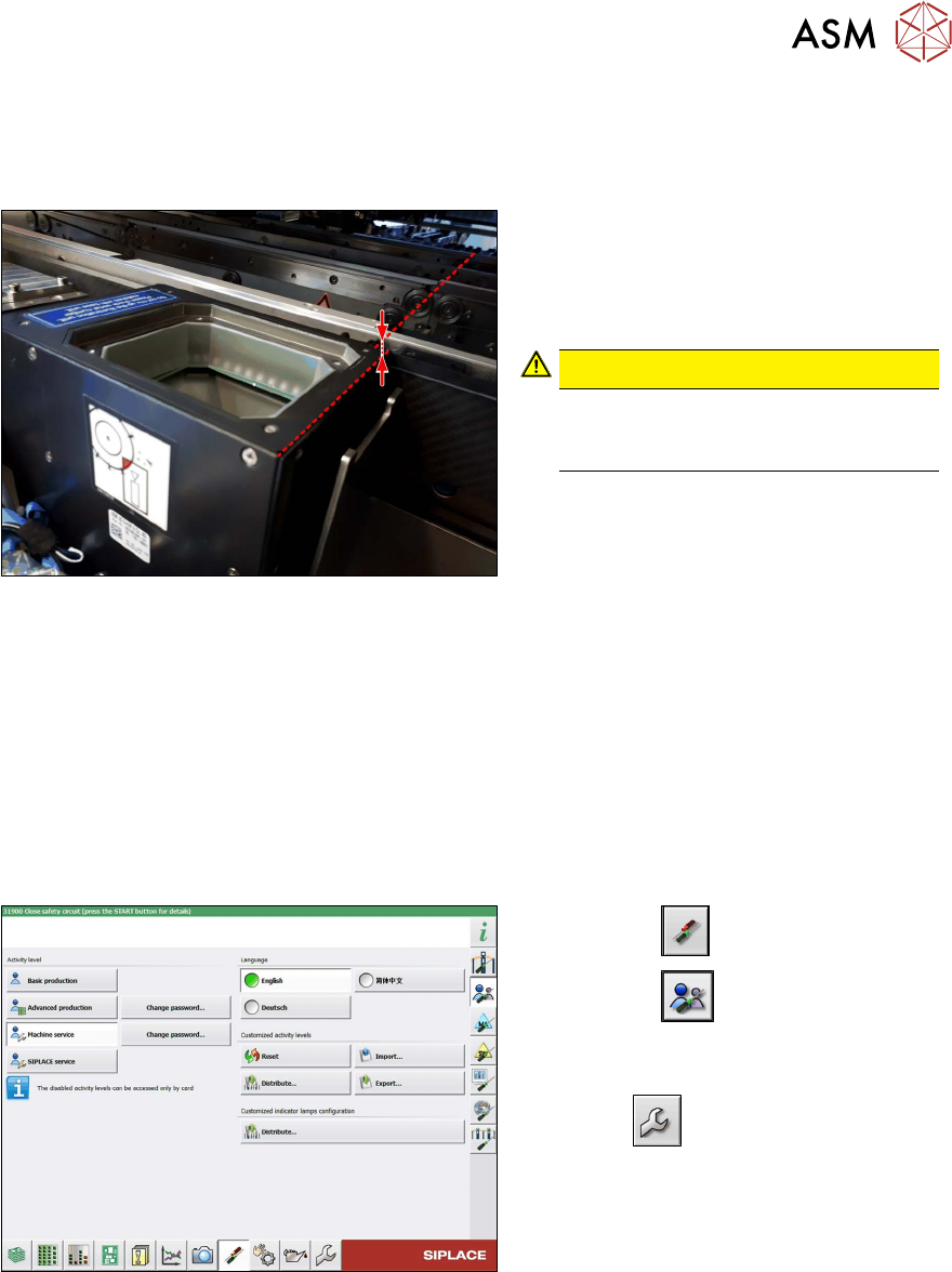
Fig.27: Review
► Carefully place the camera upper sec-
tion (illumination unit) onto the camera
lower section.
Make sure that the camera upper sec-
tion is pushed in as far as the stop.
CAUTION!
The upper edges of the cameras
must be underneath the conveyor
top edge.
.
► Make sure that the glass surface is clean. Clean the mirror/glass surface with a microfiber
cloth, if necessary.
► If the COT insert has been moved or removed, fit this and the side cover again.
4.1.2 "Replacing the SX1/SX2 COT insert assembly" [}82]
► Hook the waste tape slide back into place.
► Make sure that there are no objects in the travel area of the gantry and remove any which are.
► Start the machine and move the component trolley back into the machine.
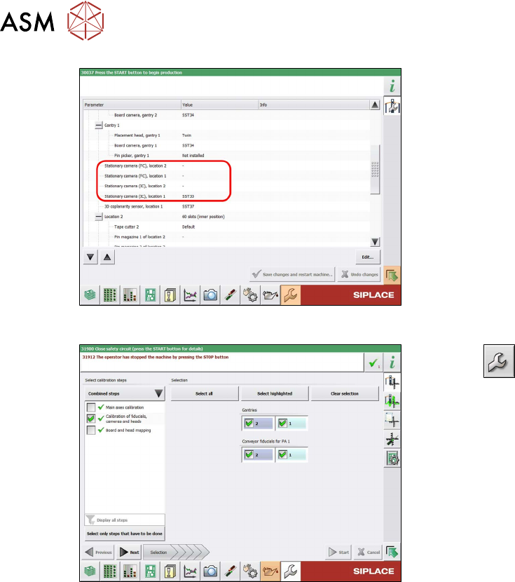
Configuration and calibration
Fig.28: Select operator level
► Select the button.
► Select the button.
► Switch over to the operator level Ma-
chine service.
ð The button will be shown.
3 Installation
3.8 Final work
80 Assembly Instructions / Montageanleitung SIPLACE SX1/SX2 V3 Stationäre Kamera Typ 25/33 (GigE) Stationary
Camera Type 25/33 (GigE) 03/2021
Fig.29: Configuration
► Configure the installed camera, at the
relevant location, in the station software
(Machine configuration
menu).
Fig.30: Calibration
► Select --> Automatic Cali-
bration.
► Select Calibration of fiducials, cam-
eras and heads and the relevant
gantry.
► Follow any other instructions on the
screen (e.g. prerequisites).
► Select Start.
ð After calibration, the camera will be
ready for use.
Perform the next steps, if necessary:
► Change the machine configuration for the new camera in SIPLACE Pro.
► Perform placement program optimization for the line.
4 Appendix
4.1 Excerpts from the Service Manual
Assembly Instructions / Montageanleitung SIPLACE SX1/SX2 V3 Stationäre Kamera Typ 25/33 (GigE) Stationary
Camera Type 25/33 (GigE) 03/2021
81
4 Appendix
4.1 Excerpts from the Service Manual
The following chapters are excerpts from the service manual for your machine. If required, further
information is provided there.
●
Service Manual SIPLACE SX1/SX2 V3 [DE:00198707‑xx] [EN:00198708‑xx]
4.1.1 Replacing the Waste Tape Chute
Parts, equipment and tools
Select the appropriate waste tape slide:
Assembly Waste tape slide
COT insert 60 [03059353-xx] Waste slide SX1/2 COT60 [03064026-xx]
COT insert 30 [03067206-xx] Waste slide SX1/2 COT30 [03073312-xx]
Removal
► Switch off the machine, disconnect it from the power supply and secure it to prevent
unauthorized reactivation.
1.2 "Preparatory work..." [}55]
► Unhook the waste tape slide.
Installation
► Hook the waste tape slide into place.
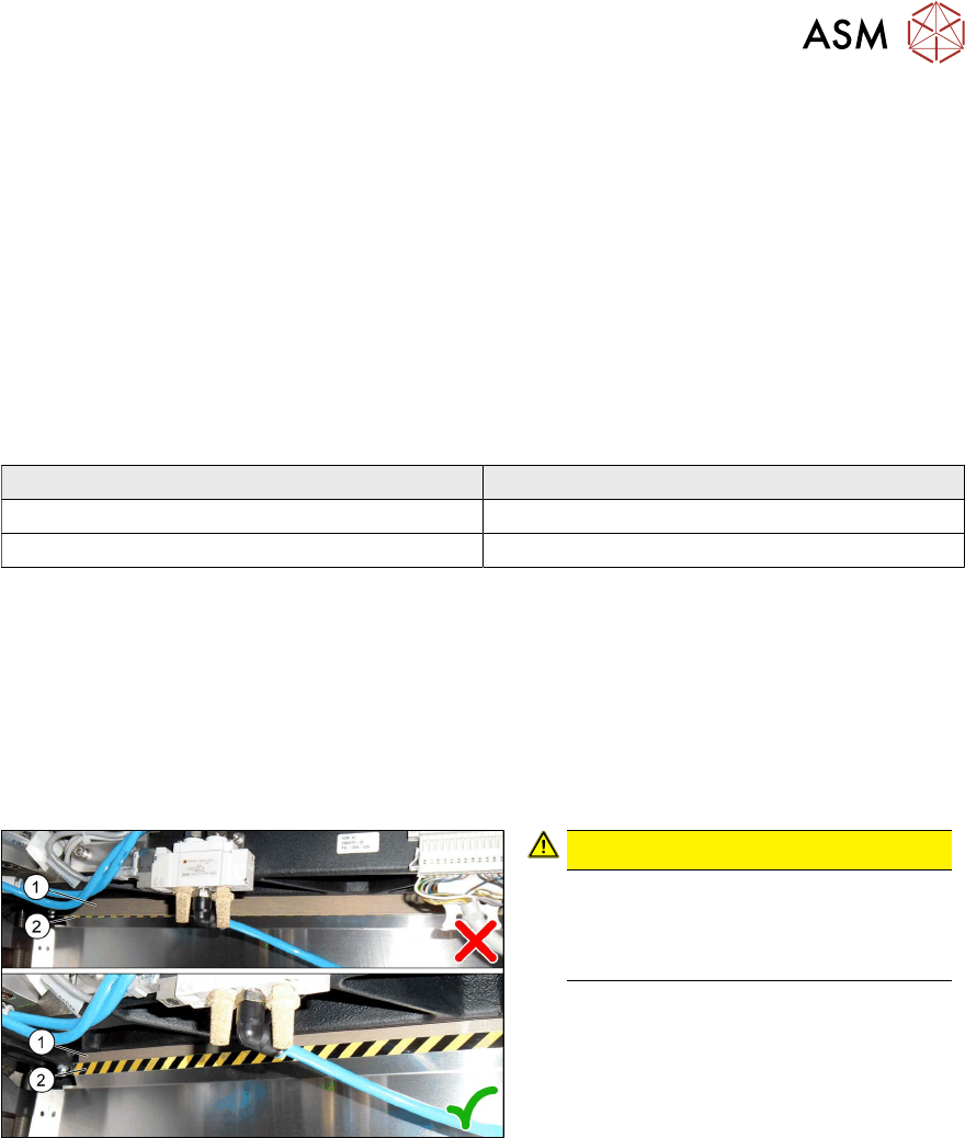
Fig.31: Plastic strips
CAUTION!
Make sure that the plastic strips(1) are
located behind the plate(2)
.
The black-yellow hatched label must
be completely visible.
.