00198706-01_AI_Stationaere_Kamera_25_33_GigE_SXV3_DE_EN.pdf - 第78页
3 Installation 3.7 Fitting the reject bin (FC camera only) 78 Assembly Instructions / Montageanleitung SIPLACE SX1/SX2 V3 Stationäre Kamera Typ 25/33 (GigE) Stationary Camera Type 25/33 (GigE) 03/2021 Fitting the sensor …
3 Installation
3.7 Fitting the reject bin (FC camera only)
Assembly Instructions / Montageanleitung SIPLACE SX1/SX2 V3 Stationäre Kamera Typ 25/33 (GigE) Stationary
Camera Type 25/33 (GigE) 03/2021
77
3.7 Fitting the reject bin (FC camera only)
When using the "stationary camera for CPP head" option, you need to fit an additional reject bin for
components >36x36mm. This is identical to the Twin reject bin.
This reject bin is included in the delivery packages for the stationary camera and the HRK for
SIPLACE Twin.
Parts
Quantity Designation Item no.
1 Holder for reject bin P001 03063283-xx
2 ISO 4762 - M 6 x 10-A2-70 03042571-xx
1 Reject bin assembly 03072806-xx
You also need the "Verify component reject bin, SX1/2" [00519848‑xx].
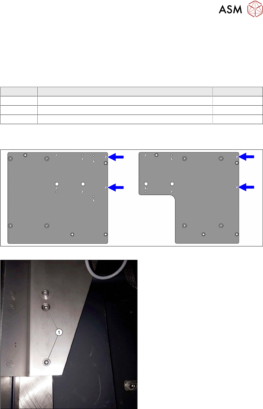
Fitting the holder
Fig.23: Reject bin screw points on the support plate assemblies
Fig.24: Holder (example of location 2 shown)
► Use the two fastening screws (1)
(M6x10) to fit the holder to the support
plate assembly.
3 Installation
3.7 Fitting the reject bin (FC camera only)
78 Assembly Instructions / Montageanleitung SIPLACE SX1/SX2 V3 Stationäre Kamera Typ 25/33 (GigE) Stationary
Camera Type 25/33 (GigE) 03/2021
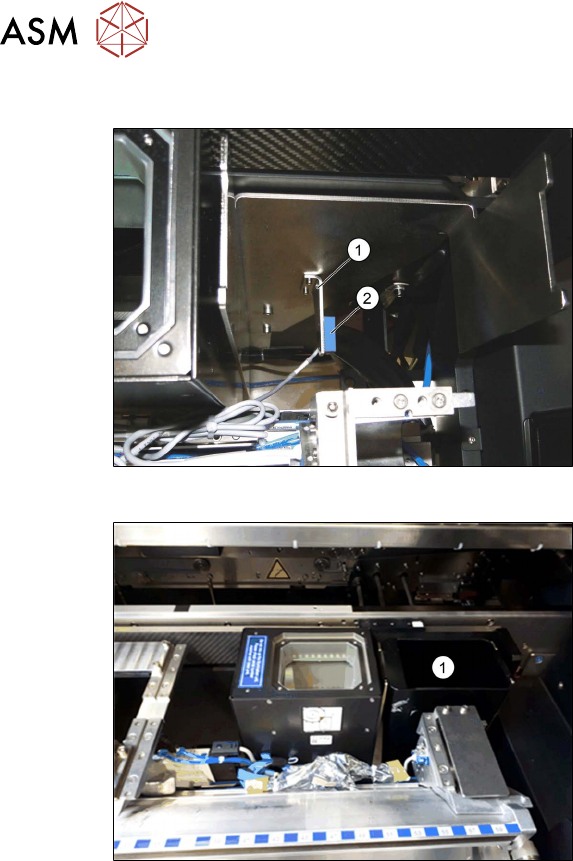
Fitting the sensor
Fig.25: Reject bin sensor
► Fit the holder(1) for the sensor, sup-
plied with the "Verify component reject
bin, SX1/2" [00519848‑xx], and fix with
two screws.
► Fit the sensor. This is located on the
COT insert.
See also the assembly instructions for
the "Verify component reject bin SX1/
SX2, DE+EN" [00196615‑xx]
Fig.26: Reject bin
► Insert the reject bin(1).
3 Installation
3.8 Final work
Assembly Instructions / Montageanleitung SIPLACE SX1/SX2 V3 Stationäre Kamera Typ 25/33 (GigE) Stationary
Camera Type 25/33 (GigE) 03/2021
79
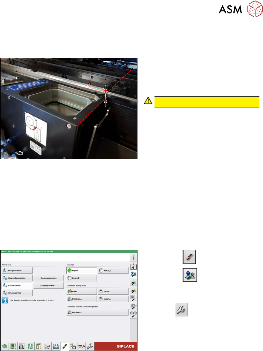
3.8 Final work
► Hook in the housing for the lower section of the camera. This is either screwed or hooked into
place, depending on your camera type.
Fig.27: Review
► Carefully place the camera upper sec-
tion (illumination unit) onto the camera
lower section.
Make sure that the camera upper sec-
tion is pushed in as far as the stop.
CAUTION!
The upper edges of the cameras
must be underneath the conveyor
top edge.
.
► Make sure that the glass surface is clean. Clean the mirror/glass surface with a microfiber
cloth, if necessary.
► If the COT insert has been moved or removed, fit this and the side cover again.
4.1.2 "Replacing the SX1/SX2 COT insert assembly" [}82]
► Hook the waste tape slide back into place.
► Make sure that there are no objects in the travel area of the gantry and remove any which are.
► Start the machine and move the component trolley back into the machine.
Configuration and calibration
Fig.28: Select operator level
► Select the button.
► Select the button.
► Switch over to the operator level Ma-
chine service.
ð The button will be shown.