00198706-01_AI_Stationaere_Kamera_25_33_GigE_SXV3_DE_EN.pdf - 第82页
4 Appendix 4.1 Excerpts from the Service Manual 82 Assembly Instructions / Montageanleitung SIPLACE SX1/SX2 V3 Stationäre Kamera Typ 25/33 (GigE) Stationary Camera Type 25/33 (GigE) 03/2021 4.1.2 Replacing the SX1/SX2 CO…
4 Appendix
4.1 Excerpts from the Service Manual
Assembly Instructions / Montageanleitung SIPLACE SX1/SX2 V3 Stationäre Kamera Typ 25/33 (GigE) Stationary
Camera Type 25/33 (GigE) 03/2021
81
4 Appendix
4.1 Excerpts from the Service Manual
The following chapters are excerpts from the service manual for your machine. If required, further
information is provided there.
●
Service Manual SIPLACE SX1/SX2 V3 [DE:00198707‑xx] [EN:00198708‑xx]
4.1.1 Replacing the Waste Tape Chute
Parts, equipment and tools
Select the appropriate waste tape slide:
Assembly Waste tape slide
COT insert 60 [03059353-xx] Waste slide SX1/2 COT60 [03064026-xx]
COT insert 30 [03067206-xx] Waste slide SX1/2 COT30 [03073312-xx]
Removal
► Switch off the machine, disconnect it from the power supply and secure it to prevent
unauthorized reactivation.
1.2 "Preparatory work..." [}55]
► Unhook the waste tape slide.
Installation
► Hook the waste tape slide into place.
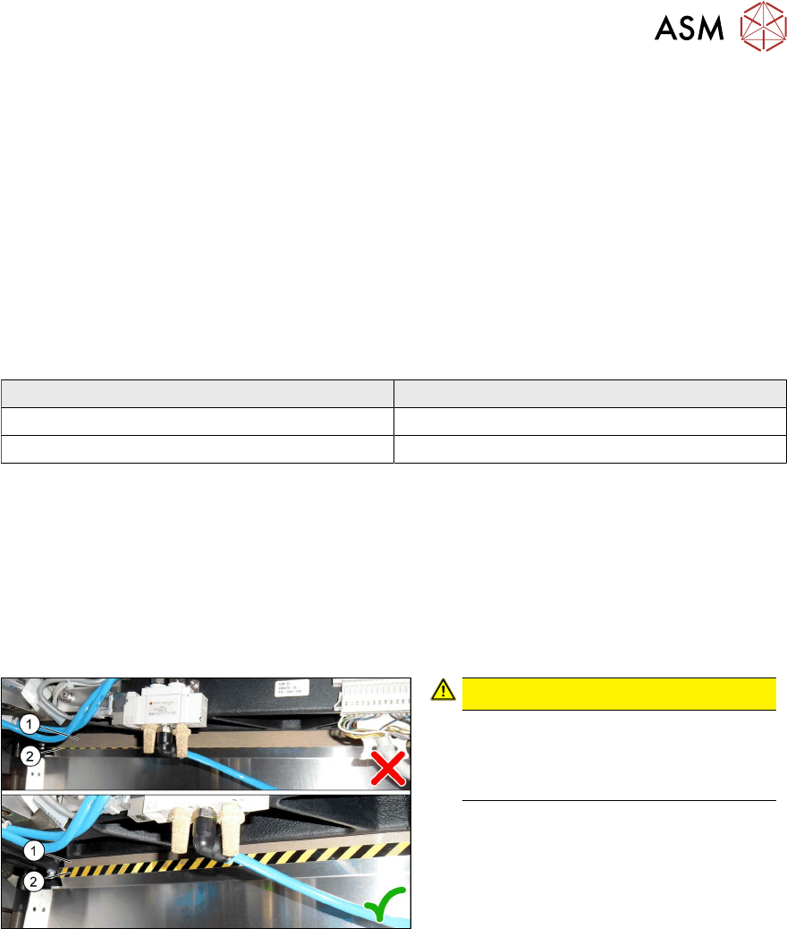
Fig.31: Plastic strips
CAUTION!
Make sure that the plastic strips(1) are
located behind the plate(2)
.
The black-yellow hatched label must
be completely visible.
.
4 Appendix
4.1 Excerpts from the Service Manual
82 Assembly Instructions / Montageanleitung SIPLACE SX1/SX2 V3 Stationäre Kamera Typ 25/33 (GigE) Stationary
Camera Type 25/33 (GigE) 03/2021
4.1.2 Replacing the SX1/SX2 COT insert assembly
Parts, equipment and tools
●
Standard: COT insert for SX1/SX2 [03059353-xx]
With WPC: COT insert 30 [03067206-xx]
●
Mounting tool [03072615-xx]
●
Suitable lifting device (e.g. Flexolift 175 [03072616-xx])
Removal
► Switch off the machine, disconnect it from the power supply and secure it to prevent
unauthorized reactivation.
1.2 "Preparatory work..." [}55]
► Unplug all electrical and pneumatic connections from the nozzle changer. You may like to
mark their positions, to make clear assignment easier later on.
► Remove the nozzle changer.
► Remove the cutter from the machine.
► Dismantle the downholder.
4.1.2.1
"Fitting the Downholder" [}84]
► Unplug all electrical and pneumatic connections from the COT insert. These are in sectors 2
and 4, on the right of the location. You may like to mark their positions, to make clear assign-
ment easier later on.
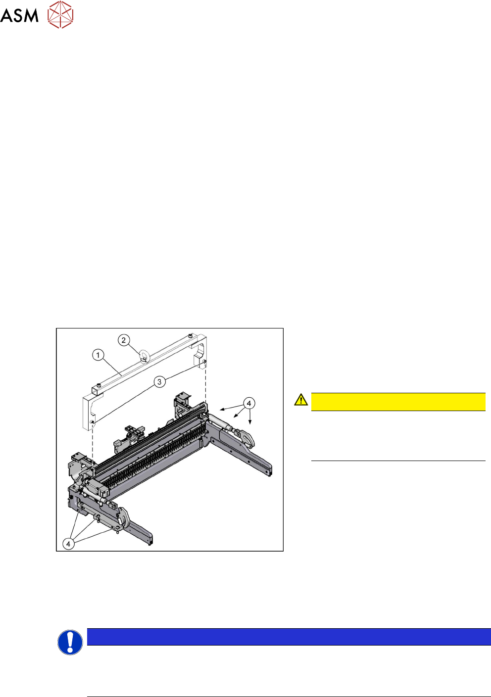
Fig.32: Fastening screws
1. Mounting tool
2. Eyelet
3. Fastening screws for mounting tool
4. Fastening screws for COT insert
CAUTION!
Heavy machine part!
The COT insert is heavy. To lift it out,
you will need to use the mounting tool
and a suitable lifting device.
.
► Attach the mounting tool to the fixtures provided on the COT insert.
► Remove the six screws fastening the COT insert.
► Fix the lifting device to the eyelet of the mounting tool.
NOTICE
Marking the installation position
The COT insert can be installed at different positions (inner/outer) in the machine location.
Mark the position of your COT insert, to ensure that this is subsequently returned to its ori-
ginal position.
► Lift the complete COT insert out of the machine and place it on a suitable surface (e.g. four
wooden blocks).
Make sure not to damage any valves, connection cables, hoses, etc.

4 Appendix
4.1 Excerpts from the Service Manual
Assembly Instructions / Montageanleitung SIPLACE SX1/SX2 V3 Stationäre Kamera Typ 25/33 (GigE) Stationary
Camera Type 25/33 (GigE) 03/2021
83
Installation
Follow the removal instructions in reverse order for installation. Also observe the following instruc-
tions:
► Attach the mounting tool to the new COT insert and lift it into the machine, with the help of the
lifting device.
► Make sure not to damage the cables and hoses.
► Observe the instructions in section 4.1.2.1 "Fitting the Downholder" [}84].
► Hook the waste tape slide into place. Pay particular attention to the plastic strips and the fuses
(if present).