00198519-03_UM_LDU_2_X_DE_EN_CHS-ZH.pdf - 第127页
3 Function description and structure 3.2 Structure User Manual / Bedienungsanleitung / 用户手册 SIPLACE Linear Dipping Unit 2 X 05/2020 127 3.2.2 Squeegee 1. Downholder 2. Cover 3. Flux tank The removable cover of the flux t…
3 Function description and structure
3.2 Structure
126 User Manual / Bedienungsanleitung / 用户手册 SIPLACE Linear Dipping Unit 2 X 05/2020
3.2 Structure
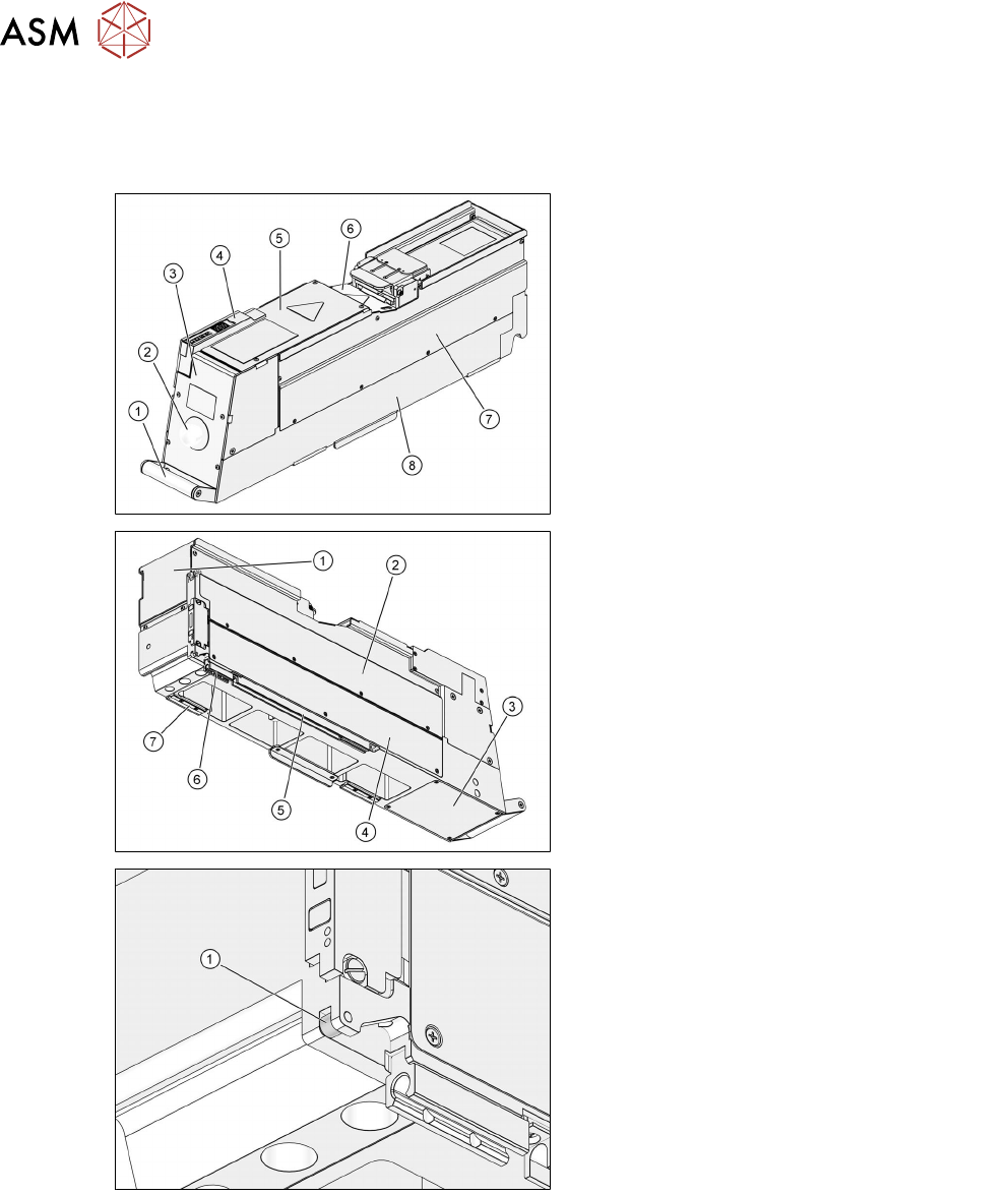
3.2.1 Housing
1. Handle
2. Emergency stop button
3. Rear cover
4. User interface
5. Top cover
6. Cover of coupling
7. Right side panel
8. Body
1. Front cover
2. Left side panel
3. Bottom cover
4. Cover of control board
5. Rear slide bar
6. Front slide bar
7. Support block
1. Locking roll
3 Function description and structure
3.2 Structure
User Manual / Bedienungsanleitung / 用户手册 SIPLACE Linear Dipping Unit 2 X 05/2020 127
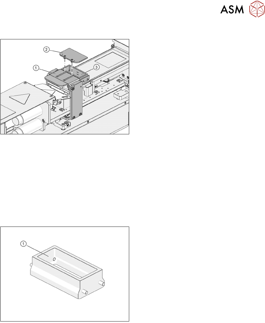
3.2.2 Squeegee
1. Downholder
2. Cover
3. Flux tank
The removable cover of the flux tank prevents anything from falling in the flux tank. The down-
holder holds the flux tank in the correct position. By pressing on the downholder the flux tank can
easily be removed.
These flux tanks are available for the LDU:
●
Standard tank [00117107-xx]
●
Small tank [00117108-xx]
Flux tank for LDU 2 X with Auto Cavity option
Using an Auto Cavity dipping plate requires a special flux tank [03154869-xx] which covers a larger
area on the dipping plate. This is important for catching any overflow of flux material if the cavity
plate moves up for application.
1. Flux tank for Auto Cavity dipping plate
3 Function description and structure
3.2 Structure
128 User Manual / Bedienungsanleitung / 用户手册 SIPLACE Linear Dipping Unit 2 X 05/2020
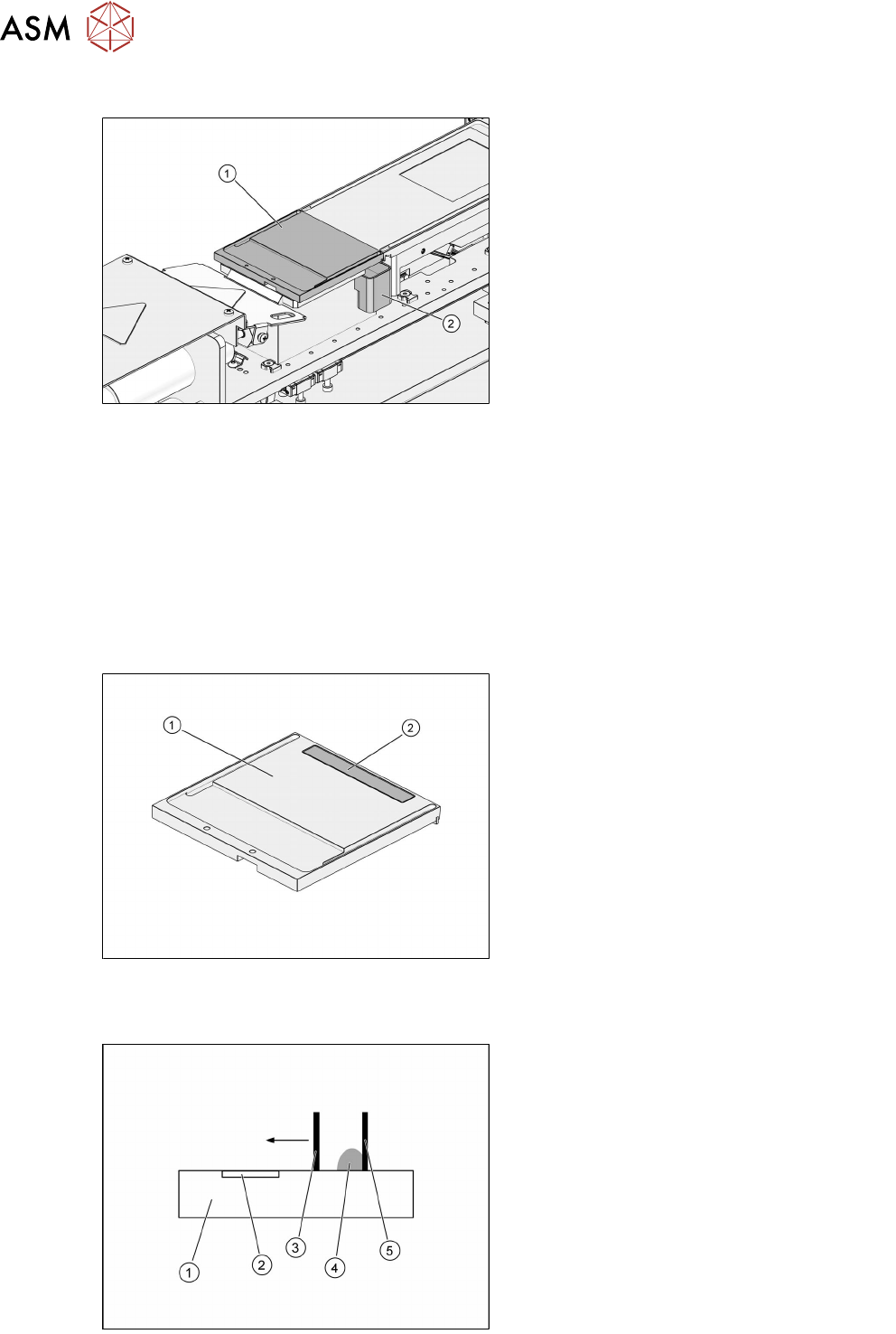
3.2.3 Park plate and drip tray
1. Park plate
2. Drip tray
The park plate is held in place by permanent magnets. The shape of the drip tray is asymmetric so
that it cannot be fitted wrongly. Two sensors on the base determine whether a park plate or a drip
tray is fitted.
3.2.4 Flux Level Sensor
During production, the amount of flux in the flux tank decreases. If the amount of flux is too low to
fill the cavity in the plate, components can no longer be coated with flux to the quality required. To
avoid this, the amount of flux in the flux tank can be monitored by the Flux Level Sensor.
The Flux Level Sensor of the LDU 2 X is based on a capacitive structure, which generates an elec-
trical field. The capacitive structure is part of the top side layout of a PCB integrated in the park
plate.
1. Park plate
2. Flux Level Sensor
The capacitance of the Flux Level Sensor is affected by the permittivity of the flux or by any other
capacitive structure like the flux tank. When moving the flux tank, the flux forms a wave inside the
flux tank.
1. Park plate
2. Flux Level Sensor
3. Front wall of the flux tank
4. Flux
5. Rear wall of the flux tank