00198519-03_UM_LDU_2_X_DE_EN_CHS-ZH.pdf - 第163页
4 Operation 4.2 Performing planarity check User Manual / Bedienungsanleitung / 用户手册 SIPLACE Linear Dipping Unit 2 X 05/2020 163 4.2 Performing planarity check NOTICE Target group: setup operator The procedure described i…
4 Operation
4.1 Settings in SIPLACE Pro
162 User Manual / Bedienungsanleitung / 用户手册 SIPLACE Linear Dipping Unit 2 X 05/2020
4.1.12 Setting the warm-up cycles and the squeegee speed
During the warm-up cycle, the LDU performs a set number of squeegee processes to prepare the
flux.
The squeegee speed is the speed with which the squeegee axis applies the flux in the cavity.
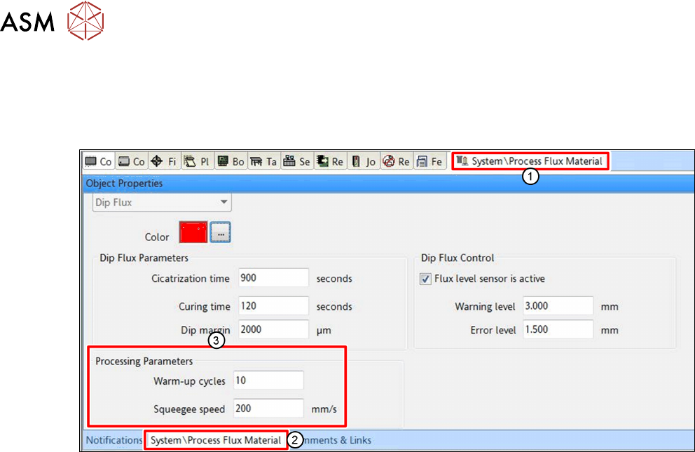
► In SIPLACE Pro, click on the tab of the relevant flux(1).
► Click on the tab of the flux(2) in the Object Properties view.
► Enter the number of squeegee processes which are to be performed during the warm-up
cycle in the Warm-up cycles
entry field in the Processing Parameters area (3).
► Enter the squeegee speed in millimeter per second [mm/s] in the Squeegee speed entry field
in the Processing Parameters
area (3).

4 Operation
4.2 Performing planarity check
User Manual / Bedienungsanleitung / 用户手册 SIPLACE Linear Dipping Unit 2 X 05/2020 163
4.2 Performing planarity check
NOTICE
Target group: setup operator
The procedure described is a task that occurs irregularly and should only be carried out by
a trained operator with special knowledge (setup operator).
To ensure that the components can be dipped into the medium over the entire dipping area, it is
important that the dipping area is not tilted. You therefore need to align the LDU parallel to the
gantry or to the placement head of the placement machine. The LDU has two adjustment screws
for this purpose. The correct position of the cavity can be checked with the help of the measure-
ment run in the station software.
The measurement run sets the dipping plate parallel to the gantry. It does NOT determine the level
of the dipping plate compared to the ground. It is therefore important that the machine in which the
LDU is used is standing absolutely level. This is important, if thin flux should not run out of the cav-
ity. If the machine is not level and the dipping plate is aligned parallel to the gantry, the dipping
plate will then not be level in relation to the ground.
Planarity check procedure
The placement head moves over the first measuring point in the cavity of the dipping plate. After
this, the Z-axis moves slowly downwards until the nozzle springs into place and the Z‑axis sensor
reports that the nozzle is now down on the dipping plate. The Z-axis then moves up again. The sys-
tem calculates the absolute height of the first measuring point.
The gantry now moves to the second measuring point. The Z-axis performs height measurement
again and now determines the relative height difference to the first measuring point. If the measure-
ment for the second measuring point is positive, measuring point2 is higher than measuring point
1. If it is negative, this means that it is lower. If the relative measurement is zero, this means that
both measuring points are at the same height. The same procedure is applied to the third measur-
ing point.
Definitions
●
Measuring point 1: reference point.
●
Absolute height [µm]: the measured height of the respective measuring point.
●
Relative height [µm]: the deviation of the absolute height of measuring point 2 or 3 to the ab-
solute height of the reference point. This value is always 0 for the reference point.
Preconditions
► The placement machine must be exactly level to the ground.
► The cavity of the dipping plate must be free of flux.
► There must be a nozzle on the placement head.
4 Operation
4.2 Performing planarity check
164 User Manual / Bedienungsanleitung / 用户手册 SIPLACE Linear Dipping Unit 2 X 05/2020
Performing planarity check
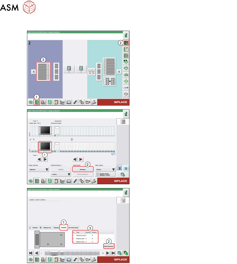
► In the station software, select the Setup
view(1) and then the Locations area (2).
► Select the Table (3) on which the LDU is
set up.
► Select the icon of the LDU(1).
► Click on the Settings... button (2).
► Select the Planarity tab(1).
► Click on the Check planarity button(2).
The machine will perform the measurement and
then show the values determined in the table
(3)
.
► Read the values.
●
The relative values for measuring points 2 and 3 are lower than +/- 50 μm: the LDU is set
correctly.
●
The relative values for measuring points 2 and 3 are higher than +/- 50 μm:
► Perform the following steps until the relative values for measuring points 2 and 3 are lower
than +/-50µm:
► Align the LDU (see 4.13 "Aligning" [}189]).
► Repeat the planarity check.