00198519-03_UM_LDU_2_X_DE_EN_CHS-ZH.pdf - 第140页
3 Function description and structure 3.3 Basic process 140 User Manual / Bedienungsanleitung / 用户手册 SIPLACE Linear Dipping Unit 2 X 05/2020 3.3.2 Thickness of flux layer The amount of flux on the component depends on the…
3 Function description and structure
3.3 Basic process
User Manual / Bedienungsanleitung / 用户手册 SIPLACE Linear Dipping Unit 2 X 05/2020 139
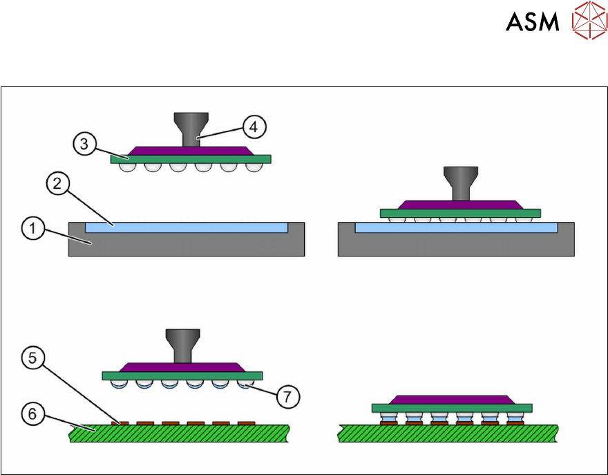
Flux application by dipping
During dipping, the component (3) is dipped with nozzle (4) into the flux by the placement machine (2)
and is then placed onto the board (6) with the contact surfaces (5). The flux must be made available in
a suitable carrier (1)
, on a surface that is flat as possible. The component is picked up from the feeder
module and is dipped into the flux. The leads or contact surfaces of the component are coated with this
flux (7)
. After this, the component is placed on the board. Thicker flux types or solder pastes can be
used for dipping.
3 Function description and structure
3.3 Basic process
140 User Manual / Bedienungsanleitung / 用户手册 SIPLACE Linear Dipping Unit 2 X 05/2020
3.3.2 Thickness of flux layer
The amount of flux on the component depends on the thickness of the flux layer in the cavity. The
layer thickness depends both on the cavity depth and the coating effect of the fluid used. The cavity
depth is engraved on the top of the dipping plate.
Influence of cavity depth on the layer thickness
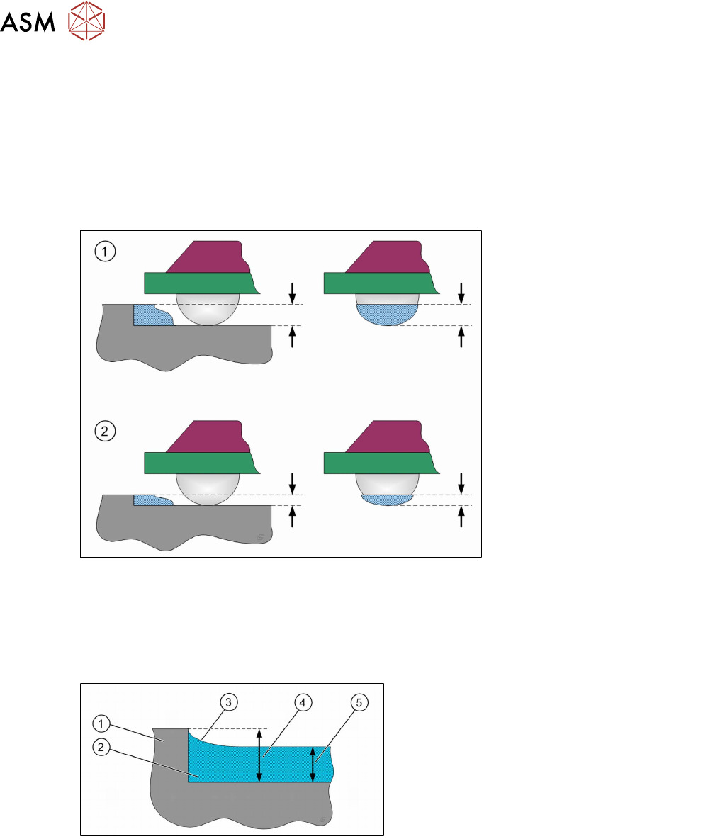
In the following diagram, the same component is dipped into various different dipping plates. The
dipping plate cavity in (1)
is deeper than in (2). This means that more flux adheres to the compo-
nent because the layer of flux is thicker here.
Influence of coating fluid on the layer thickness
The capillary effect describes the behavior of fluid as shown during the contact between solids and
capillaries e.g. narrow tubes, gaps or hollow spaces.
Example: if one dips a glass tube vertically into water, the water will rise up a little in the narrow
glass tube against the force of gravity. This effect is caused by the surface tension of the fluid itself
and the interfacial tension of the fluids with the solid surface.
1. Dipping plate
2. Flux
3. Hollow
4. Cavity depth in the dipping plate
5. Remaining flux height
Multiple measurements lead to a value for reduction of the layer thickness. This value shows that
the flux layer thickness is roughly 2/3 of the cavity depth i.e. the layer thickness is reduced by about
1/3. Since the value of 2/3 is a rough estimate, the exact amount of flux which stays on the compo-
nent must be determined in tests. In very critical processes, dipping plates with a customized cavity
depth can be supplied.
3 Function description and structure
3.3 Basic process
User Manual / Bedienungsanleitung / 用户手册 SIPLACE Linear Dipping Unit 2 X 05/2020 141
Influence of coating fluid on the dipping area
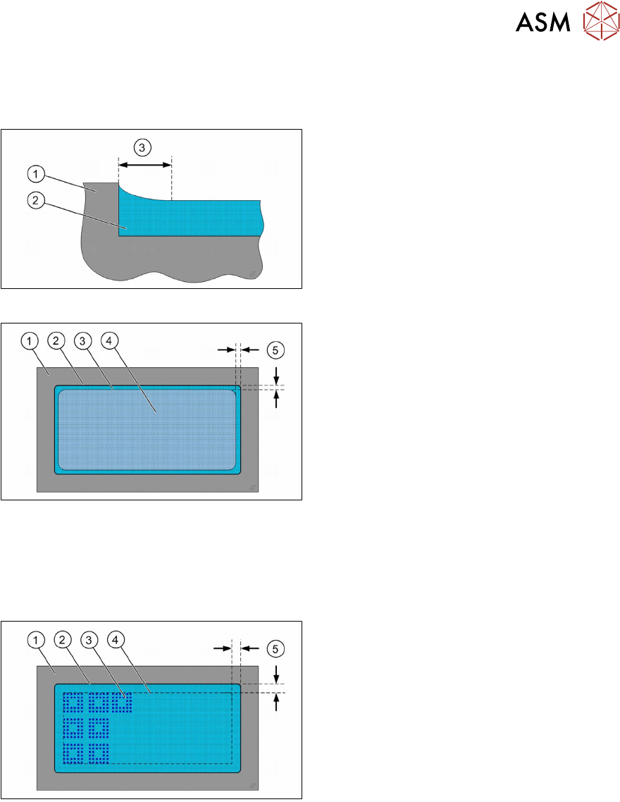
A hollow is formed in the flux at the edge of the cavity. This has a width of about one to two milli-
meters.
1. Dipping plate
2. Flux
3. Width of hollow
This means that the dipping plate area which can be used is smaller than the cavity itself.
1. Dipping plate
2. Cavity
3. Hollow
4. Dipping area, determined by the hollow
5. Edge area, determined by the hollow
This effect is taken into account in the station software. The placement machine automatically
keeps an edge when dipping components. The size of this edge is determined by the SIPLACE Pro
parameter dip margin
.
Example: With a dip margin of 3mm the dipping area is therefore 6 mm smaller than the cavity it-
self. The cavity has a size of 75 mm x 55 mm, the available dipping area only a size of 69 mm x 49
mm.
1. Dipping plate
2. Cavity
3. Print of dipped component in the flux
4. Dipping area, determined by the software
5. edge area, determined by the SIPLACE
Pro parameter dip margin