00198519-03_UM_LDU_2_X_DE_EN_CHS-ZH.pdf - 第138页
3 Function description and structure 3.3 Basic process 138 User Manual / Bedienungsanleitung / 用户手册 SIPLACE Linear Dipping Unit 2 X 05/2020 3.3 Basic process Th e f oll ow ing se ct ion d esc rib es th e d ipp in g p ro …
3 Function description and structure
3.2 Structure
User Manual / Bedienungsanleitung / 用户手册 SIPLACE Linear Dipping Unit 2 X 05/2020 137
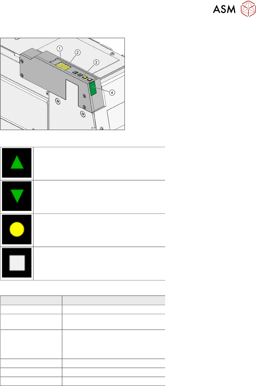
3.2.10 User interface
1. 7 segment display 1/2 (operation mode,
error mode, emergency stop)
2. 7 segment display 3/4 (error number,
squeegee speed, remaining cycles, emer-
gency stop)
3. Function keys
4. Status LED
Function keys
Up key: Pressing it briefly switches to the next
operating mode (P0
→ P1 → P2 → …). Pressing
it long while in mode P2
switches to the activity
level Advanced production
(P2→P3).
Down key: Switches to the previous operating
mode (P2
→P1→ P0…). Clears the current
error in the Er
display.
<Select> key: Selects the operating mode dis-
played, starts an operation, switches on the 7
segment displays.
<Adjust> key: Sets a parameter, clears an error,
halts the warm-up cycle.
Status LED
Color of status LED Operating state of the LDU
Green (permanent) Ready for operation
Amber (permanent) Warning. The LDU will change soon to
the state "Not ready".
Red (permanent) LDU not initialized, not warmed up or
in error mode. The 7 segment display
1/2 shows the corresponding error
number.
Off Not ready for operation
Green (fast flashing) Software download
Red (fast flashing) Application software invalid
Operating the LDU with the help of the function keys is described in chapter 4.8 "Operating the con-
trol unit via user interface" [}179].
3 Function description and structure
3.3 Basic process
138 User Manual / Bedienungsanleitung / 用户手册 SIPLACE Linear Dipping Unit 2 X 05/2020
3.3 Basic process
The following section describes the dipping process and the parameters which influence this process.
3.3.1 Usage of flux
To improve the solderability of corrosive components or components with complex structures, the
contact surfaces of these components should be coated with additional flux during production. This
increases the quality of the soldered connection. The flux is applied to the relevant contact surfaces
of the component or board during the placement procedure. The two most common procedures are
dispensing
and dipping. In addition, there are other procedures such as printing, stamping, spray-
ing, brush application etc.
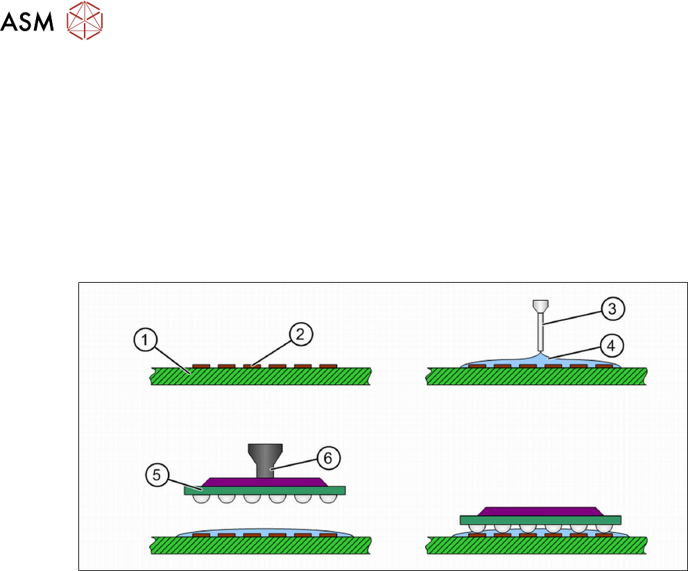
Flux application by dispensing
During dispensing, the flux is applied directly onto the board (1). A needle (3) is positioned exactly
over the soldered connection or the contact surfaces (2)
and a defined amount of flux (4) is applied
to the soldered connection. A film forms on the soldered connection, in which the component (5)
is
placed with the tweezers (6)
. Only thin flux types are suitable for dispensing.
3 Function description and structure
3.3 Basic process
User Manual / Bedienungsanleitung / 用户手册 SIPLACE Linear Dipping Unit 2 X 05/2020 139
Flux application by dipping
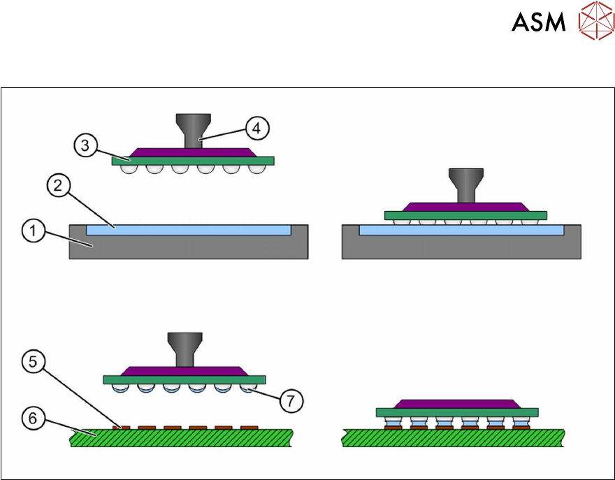
During dipping, the component (3) is dipped with nozzle (4) into the flux by the placement machine (2)
and is then placed onto the board (6) with the contact surfaces (5). The flux must be made available in
a suitable carrier (1)
, on a surface that is flat as possible. The component is picked up from the feeder
module and is dipped into the flux. The leads or contact surfaces of the component are coated with this
flux (7)
. After this, the component is placed on the board. Thicker flux types or solder pastes can be
used for dipping.