00198519-03_UM_LDU_2_X_DE_EN_CHS-ZH.pdf - 第153页
4 Operation 4.1 Settings in SIPLACE Pro User Manual / Bedienungsanleitung / 用户手册 SIPLACE Linear Dipping Unit 2 X 05/2020 153 ► Enter the appropriate coordinates and the cavity depth of every cavity in the corresponding f…
4 Operation
4.1 Settings in SIPLACE Pro
152 User Manual / Bedienungsanleitung / 用户手册 SIPLACE Linear Dipping Unit 2 X 05/2020
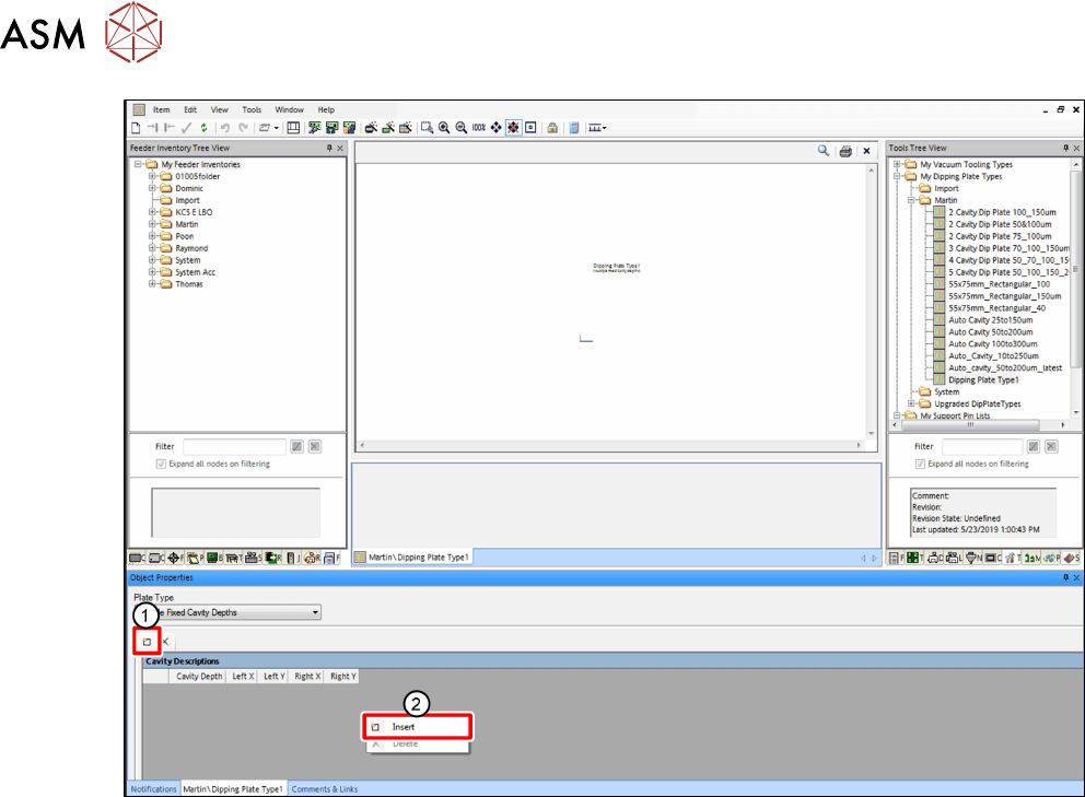
► Click on the Insert icon(1) or, alternatively, right-click on the gray area and select Insert from
the menu(2)
.
A new row representing a cavity is inserted in the table.
► Repeat this step to insert multiple rows (cavities) to the table.
4 Operation
4.1 Settings in SIPLACE Pro
User Manual / Bedienungsanleitung / 用户手册 SIPLACE Linear Dipping Unit 2 X 05/2020 153
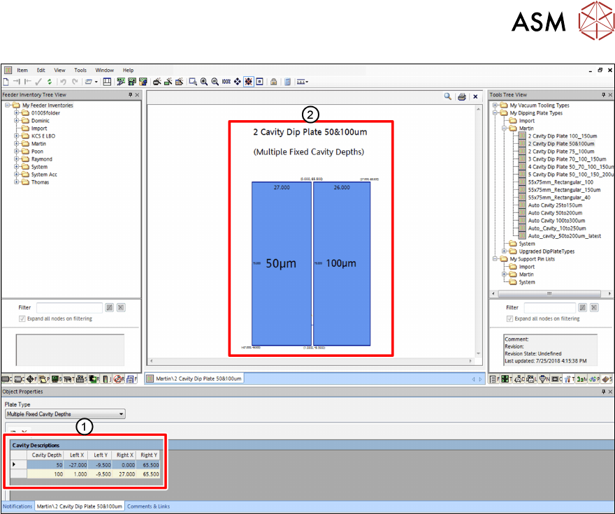
► Enter the appropriate coordinates and the cavity depth of every cavity in the corresponding
fields(1)
.
Cavity Depth: Depths of the cavities
Left X / Left Y: Lower left corners of the cavities
Right X / Right Y: Upper right corners of the cavities
The coordinates and the cavity depths of the cavities are displayed in the display area(2).
4 Operation
4.1 Settings in SIPLACE Pro
154 User Manual / Bedienungsanleitung / 用户手册 SIPLACE Linear Dipping Unit 2 X 05/2020
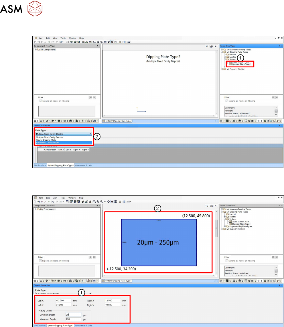
Defining an Auto Cavity dipping plate (only for LDU 2 X with Auto Cavity option)
► In the Tools Tree View, select the dipping plate to be defined(1).
► In the Object Properties area, select Adjustable Cavity Depth from the Plate Type
menu(2).
► Enter the appropriate coordinates and the cavity depth range in the corresponding fields(1).
Left X / Left Y: Lower left corner of the cavity
Right X / Right Y: Upper right corner of the cavity
Minimum / Maximum Cavity Depth: Travel range of the cavity plate
The coordinates and the depth range of the cavity are displayed in the display area(2).