00198519-03_UM_LDU_2_X_DE_EN_CHS-ZH.pdf - 第145页
4 Operation 4.1 Settings in SIPLACE Pro User Manual / Bedienungsanleitung / 用户手册 SIPLACE Linear Dipping Unit 2 X 05/2020 145 4 Operation 4.1 Settings in SIPLACE Pro NOTICE Target group: setup operator The procedure descr…
3 Function description and structure
3.3 Basic process
144 User Manual / Bedienungsanleitung / 用户手册 SIPLACE Linear Dipping Unit 2 X 05/2020
3.3.6 Dipping process and dwell time
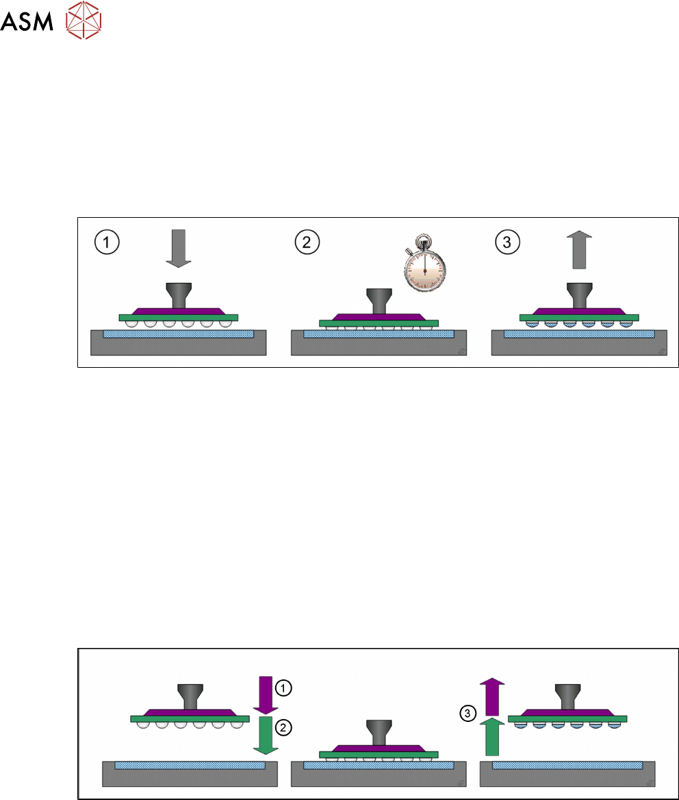
The dipping process in placement machines roughly consists of the following steps:
1. Pick component up from the relevant feeder module
2. Dipping component in the flux
3. Check and center component with the Vision system
4. Place component on the board
The detailed dipping procedure (step 2) consists of the following steps:
1. The placement head moves with the component over the LDU to an unused part of the dip-
ping area. The placement head moves down until the component reaches the bottom of the
cavity.
2. The down sensor for the placement head starts a dwell time.
3. After the end of the dwell time, the placement head moves up again.
During the dwell time, the flux can coat the component on the parts which have been dipped into it.
The dwell time can be set in the line software: 4.1.7
"Setting the dipping sequence and the dwell
time" [}158]. The correct dwell time must be determined through tests.
3.3.7 Creep distance
Depending on the viscosity of the flux used, it can be necessary to adjust the speed down or speed
up when dipping into the cavity. Components which get stuck in the flux of the cavity when the
nozzle moves up indicate that the speed up is too high. A speed down that is too high can lead to
uneven wetting of the component balls/bumps.
The distance between the surface of the cavity depth and the creep point is the creep distance.
(1) The placement head moves down with normal speed until it reaches the adjustable creep point
where it slows down to the adjustable speed down value.
(2) The placement head moves down with the speed down until it reaches the surface of the cavity
depth.
(3) The placement head moves up with the adjustable speed up until it reaches the creep point
where it accelerates to normal speed.
Creep point, speed down and speed up for each component and flux are set in the line software:
4.1.9
"Setting the creep distance" [}160].
4 Operation
4.1 Settings in SIPLACE Pro
User Manual / Bedienungsanleitung / 用户手册 SIPLACE Linear Dipping Unit 2 X 05/2020 145
4 Operation
4.1 Settings in SIPLACE Pro
NOTICE
Target group: setup operator
The procedure described is a task that occurs irregularly and should only be carried out by
a trained operator with special knowledge (setup operator).
To use the LDU in a placement order, the following settings have to be defined in SIPLACE Pro be-
fore start-up:
●
Set up the LDU
●
Define the dipping plate
●
Assign the dipping plate to the LDU
●
Define flux material
●
Assign a flux material to the LDU
●
Set the parameters for the Flux Level Sensor
●
Dipping parameters for the components used:
– Flux material used
– Cavity depth
– Dipping sequence
– Pressing force when dipping
– Dwell time when dipping
– Travel profile when dipping
– Waiting time at placement
●
Processing Parameters for the flux used:
– Cicatrization time
– Curing time
– Flux level sensor values
– Dip margin
– Squeegee speed
– Number of squeegee cycles during warm-up
4 Operation
4.1 Settings in SIPLACE Pro
146 User Manual / Bedienungsanleitung / 用户手册 SIPLACE Linear Dipping Unit 2 X 05/2020
4.1.1 Setting up the LDU
●
Depending on the head and changeover table SIPLACE Pro checks whether the LDU can be
reached or not. A general limitation doesn’t exist.
●
SIPLACE Pro checks whether the LDU can be reached or not depending on the head and
table. There is no general limitation.
●
The LDU can be set up directly next to any feeder modules.
●
The LDU should not be configured in direct vicinity to feeder modules for very small components.
●
It is recommended not to set up any linear feeder and stick feeder modules together with the
LDU on the same changeover table.
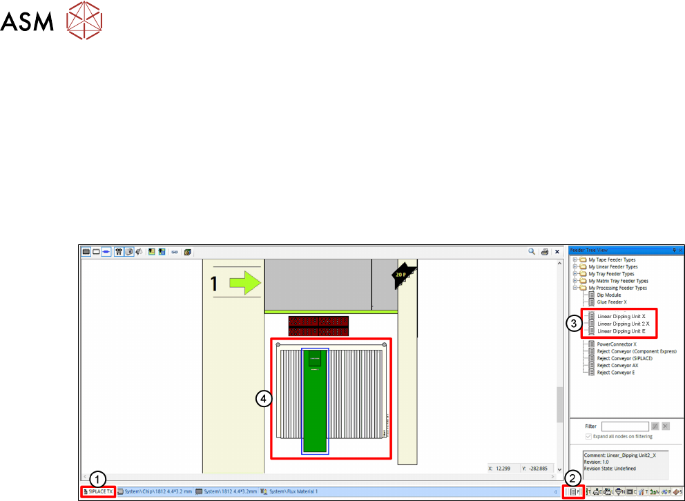
► In SIPLACE Pro, click on the Setup tab(1).
► Click on the Feeder Tree View tab(2).
► Drag the relevant LDU from the tree view(3) to the desired track of the changeover table(4).