00193794-11_VD_SSW 505.05_de en.pdf - 第43页
Software Version Description, Station Software 505.05 07/2008 Edition 5.18.1 Restrictions - Switching between "widened conveyor" mode and normal mode always involves mechanical adjustment work. - If the "L…
Software Version Description, Station Software 505.05 07/2008 Edition
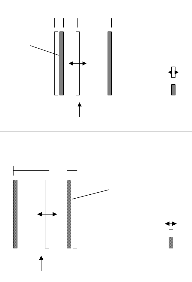
Fixed conveyor
edge
Moveable
conveyor edge
Transport direction
Conveyor
lane 1
Conveyor
lane 2
Deactivated
conveyor lane
Fig. 5-1: Dual conveyor with widened conveyor lane 1 (fixed conveyor edge on the right)
Transport direction
Fixed conveyor
edge
Moveable
conveyor edge
Conveyor
lane 2
Conveyor
lane 1
Deactivated
conveyor lane
Fig. 5-2: Dual conveyor with widened conveyor lane 2 (fixed conveyor edge on the left)
The widening of the conveyor lane is specified for a job by the programming system if this is
necessary to produce the job.
42 of 150
Software Version Description, Station Software 505.05 07/2008 Edition
5.18.1 Restrictions
- Switching between "widened conveyor" mode and normal mode always involves mechanical
adjustment work.
- If the "Long PCB" option is used, this must be deactivated before switching to "widened
conveyor" mode and the hardware for the option must be removed.
- The width of the transport lane in the line is determined by the placement station with the
narrowest conveyor lane. If, for instance, a line contains stations of the type S-27 HM and HF
with the "flexible dual conveyor", the presence of the S-27 HM means that the maximum board
width supported is 216 mm rather than 250 mm.
- The kind of stop (left- or right-side stop) can not be changed for a wide conveyor. At first, set
the normal conveyor and then change the kind of stop. (SIPLACE HS 60)
5.19 New mapping plate for HS-60, S-27
For the HS-60 and S-27 there is in addition to the standard mapping plate (216 mm) a broader
mapping plate of 380 mm. With this new mapping plate it is possible to map the dual conveyor.
5.20 Number of repetitions on picking up a component
From SIPLACE Pro 2.0 onwards, it is possible for any package form to specify how often a pickup
operation is to be repeated if it was not successful. A value 1 through 255 can be entered. If it was
not possible to pick up the package form on the machine after the specified number of repetitions,
the machine stops with a "track empty" error.
5.21 Different nozzle types on 12-nozzle C&P heads as well
As of this version 505.xx of the software, it is also possible to set up different nozzle types in the
individual garages of the nozzle changer magazines for 12-nozzle C&P heads (as was already
possible for the 6-segment C&P head).
43 of 150
Software Version Description, Station Software 505.05 07/2008 Edition
5.22 Freely definable configuration of the nozzle changer for the Twin
Head
As of version 505.xx of the software, it is possible to specify any magazine configurations for the
Twin Head nozzle changer. The predefined configurations (3/1 or 5/2 or 8/4) no longer apply. The
maximum number of magazines is limited to 12.
5.22.1 Restrictions
The Twin Head nozzle changer is not supported at the locations 4 und 2.
5.23 Recovery placement
The "Recovery Placement" function is used to continue placement of any boards still in the conveyor
of the machine after placement has been interrupted as a result of the machine coming to a
standstill after a power failure or a serious machine error.
During placement, the data for the boards located in the conveyor of the machine is automatically
stored. When the machine is restarted after a power failure or after being switched off, the operator
is asked whether assembly of the boards in the machine should be resumed. If this is confirmed, the
boards will continue to be placed (Recovery Placement).
5.23.1 Requirements
In Version 505.03 the following requirements have been added to the recovery placement (RP)
feature.
1. Configuration of recovery placement in SITEST
The recovery placement function can be activated and deactivated in a configuration dialog
(regardless of the existence of the recovery placement license):
SITEST main view –> Settings –> Recovery placement
When activating the function, you can specify the directory for the recovery placement data in
the Windows directory selection dialog.
2. Display of the status of the recovery placement data directory (SIPLACE GUI)
When recovery placement is activated (and a recovery placement license exists), the status
of the recovery placement data directory is indicated by a new icon in the main view of the
SIPLACE GUI (the status indicates whether or not data can be written to the directory).
44 of 150