SOM-1735-001.pdf - 第15页
A02 Control Dat a Fig. 1 1 Edit Window (Example) (A02-01) Speed Dat a Fig. 12 Edit Window (Example) Refer to the instruction manual "Component Library for TCM-X Series" for details. (A02-02) Selected nozzle Ref…
5.2 Parameters
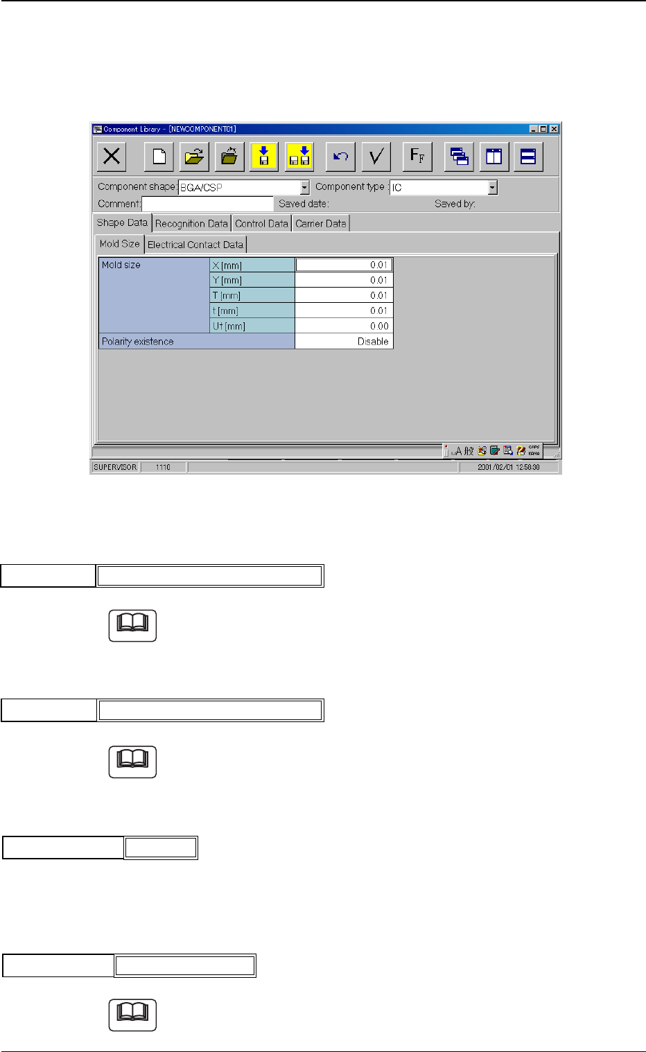
A01 Classification Data
Fig. 6 Edit Window (Example)
(A01-01) Component ID
Refer to the instruction manual "Component Library for TCM-X Series"
for details.
(A01-02) Comment
Refer to the instruction manual "Component Library for TCM-X Series"
for details.
(A01-03) Component shape
Set the shape of a component.
Select "BGA/CSP".
(A01-04) Component type
Refer to the instruction manual "Component Library for TCM-X Series"
for details.
Component ID
Fig.7
C1610M--BOYUD
Comment
Fig.8
5.2 Parameters (A01-01), (A01-02), (A01-03), (A01-04)
Note
Note
BGA/CSP
Component shape
Fig.9
0307-001 13 Tg0930-PM-SO
IC (Integrated Circuit)
Component type
Fig.10
Note
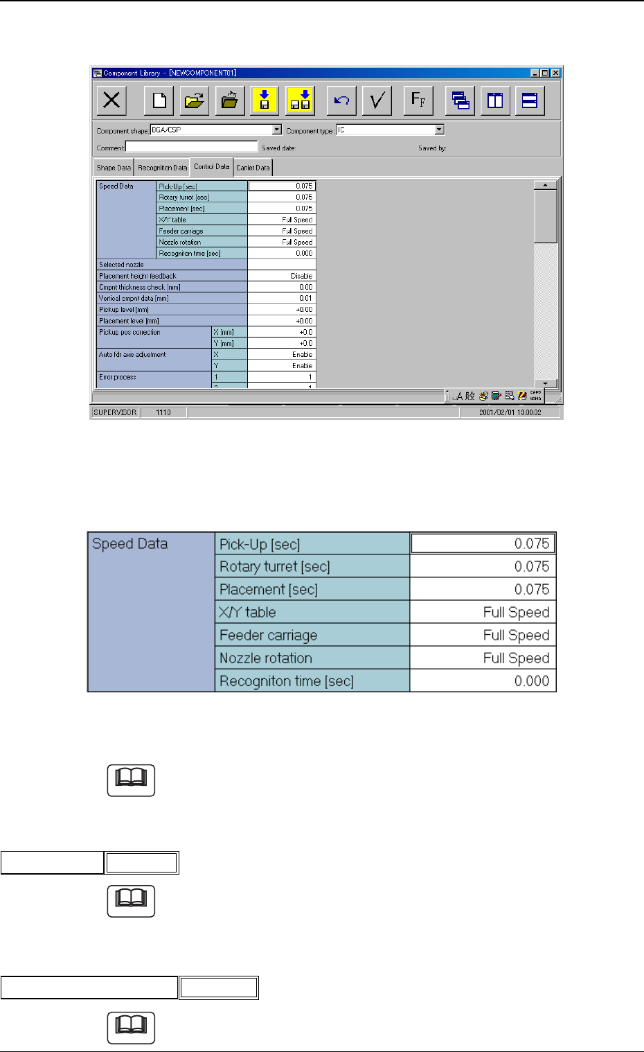
A02 Control Data
Fig. 11 Edit Window (Example)
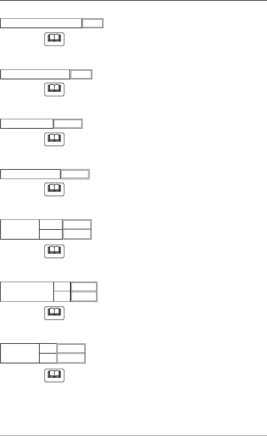
(A02-01) Speed Data
Fig. 12 Edit Window (Example)
Refer to the instruction manual "Component Library for TCM-X Series"
for details.
(A02-02) Selected nozzle
Refer to the instruction manual "Component Library for TCM-X Series"
for details.
(A02-03) Placement height feedback
Refer to the instruction manual "Component Library for TCM-X Series"
for details.
Z050
Selected nozzle
Fig.13
5.2 Parameters (A02-01), (A02-02), (A02-03)
Note
Placement height feedback
Fig.14
Disable
Note
Note
0307-001 14 Tg0930-PM-SO
(A02-04) Cmpnt thickness check [mm]
Refer to the instruction manual "Component Library for TCM-X Series"
for details.
(A02-05) Vertical cmpnt data [mm]
Refer to the instruction manual "Component Library for TCM-X Series"
for details.
(A02-06) Pickup level [mm]
Refer to the instruction manual “Component Library for TCM-X Series”
for details.
(A02-07) Placement level [mm]
Refer to the instruction manual "Component Library for TCM-X Series"
for details.
(A02-08) Pickup pos correction X [mm], Y [mm]
Refer to the instruction manual "Component Library for TCM-X Series"
for details.
(A02-09) Auto fdr axis adjustment X, Y
Refer to the instruction manual "Component Library for TCM-X Series"
for details.
(A02-10) Error process 1, 2
Refer to the instruction manual "Component Library for TCM-X Series"
for details.
Fig.18
Placement level [mm]
+0.30
1
2
1
9
Fig.21
Error process
5.2 Parameters (A02-04), (A02-05), (A02-06), (A02-07), (A02-08), (A02-09), (A02-10)
Fig.15
Cmpnt thickness check [mm]
0.00
Fig.16
Vertical cmpnt data [mm]
1.20
Fig.17
Pickup level [mm]
+0.14
X[mm]
Y[mm]
+0.0
+0.0
Fig.19
Pickup pos
correction
X
Y
Fig.B20
Auto fdr axis
adjustment
Enable
Enable
0307-001 15 Tg0930-PM-SO
Note
Note
Note
Note
Note
Note
Note