SOM-1735-001.pdf - 第37页
(3) Inspection pos X [mm], Y [mm] Set the distances between the centers of the mold and the inspection range. Unit: mm Dat a Input Range X : − 99.99 to + 99.99 Y : − 99.99 to + 99.99 Parameters can be set only when "…
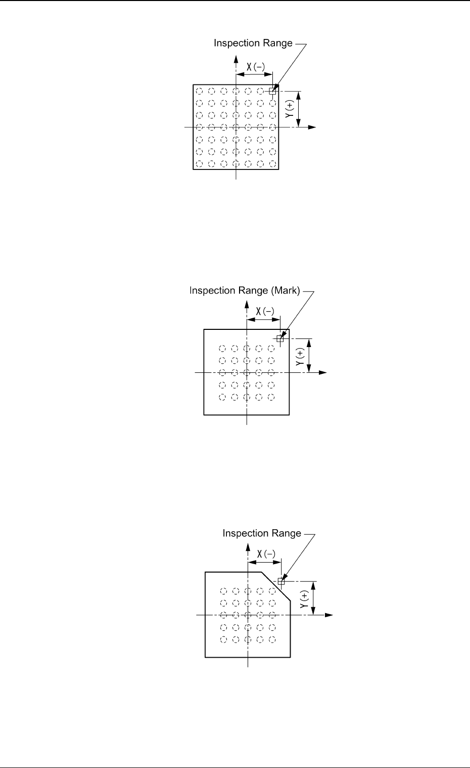
Regarding the missing ball as a polarity
Top View of Component
Fig. 81
Regarding the mark on the mold as a polarity
Top View of Component
Fig. 82
Regarding the cutout of the mold as a polarity
Top View of Component
Fig. 83
5.2 Parameters (B02-14)
0307-001 35 Tg0930-PM-SO
(3) Inspection pos X [mm], Y [mm]
Set the distances between the centers of the mold and the inspection
range.
Unit: mm
Data Input Range
X :−99.99 to +99.99
Y :−99.99 to +99.99
Parameters can be set only when "Enable (Discard)" or "En-
able (Placement)" is selected in the "Polarity detn" text box.
Top View of Component Bottom View of Component
(Ball Surface)
Fig. 85
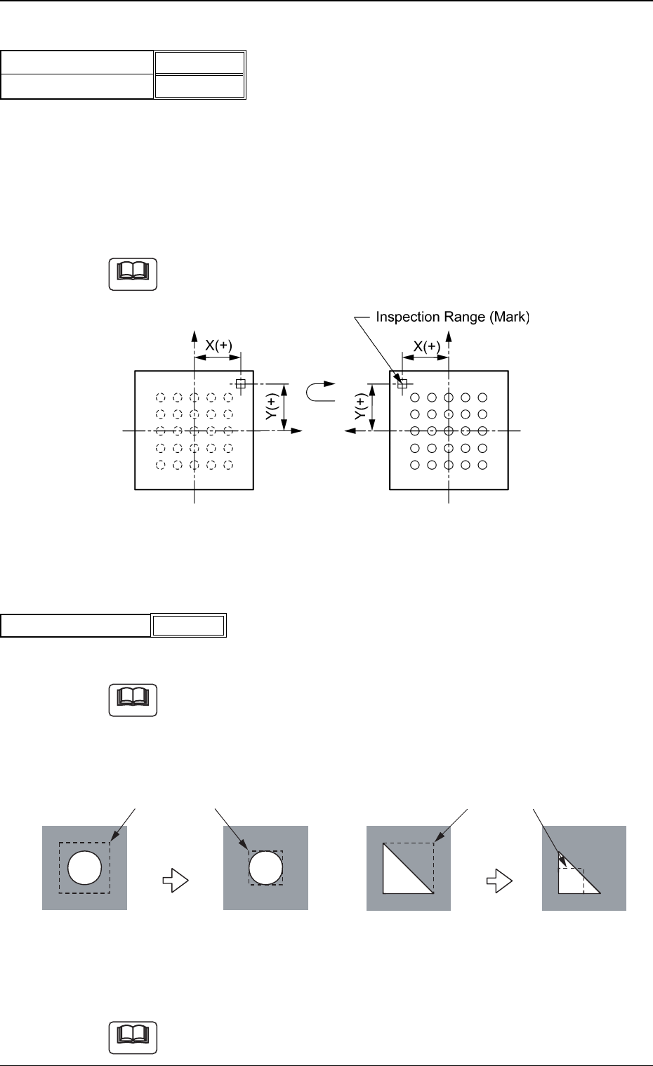
(4) Inspection range [mm]
Specify the range to be inspected.
Set a parameter as an inspection range such that the range having high
contrast is narrowed.
The average gray value in the inspection range will increase (or decrease),
making it easy to determine the polarity.
Fig. 87
Unit: mm
Data Input Range: 0.1 to 9.9
A parameter can be set only when "Enable (Discard)" or "Enable (Place-
ment)" is selected in the "Polarity detn" text box.
Fig.84
+0.00 [mm]
+0.00 [mm]
Inspection pos X [mm]
Inspection pos Y [mm]
5.2 Parameters (B02-14)
Note
Fig.86
Inspection range [mm]
0.1
Note
Note
0307-001 36 Tg0930-PM-SO
Inspection Ranges
Inspection Ranges
Impossible
Impossible
Possible
Possible
Average Gray Value = 50
Average Gray Value = 50
Average Gray Value = 100
Average Gray Value = 100
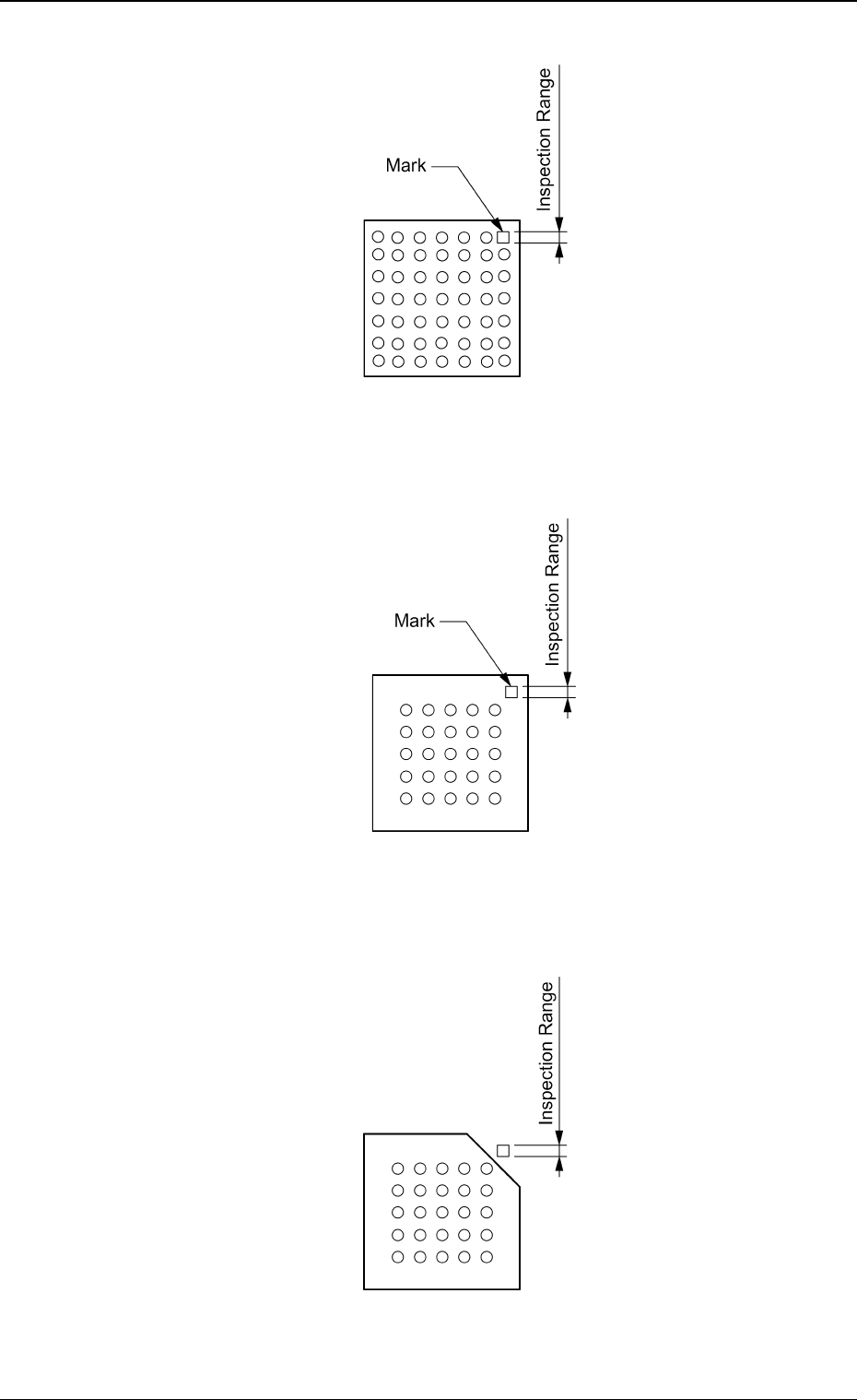
Regarding the missing ball as a polarity
Top View of Component
Fig. 88
Regarding the mark on the mold as a polarity
Top View of Component
Fig. 89
Regarding the cutout of the mold as a polarity
Top View of Component
Fig. 90
5.2 Parameters (B02-14)
0307-001 37 Tg0930-PM-SO