SOM-1735-001.pdf - 第18页
B01 Shape Dat a Fig. 25 Edit Window (Example) (B01-02) Mold size Fig. 26 Edit Window (Example) 0307-001 17 Tg0930-PM-SO 5.2 Parameters (B01-02)
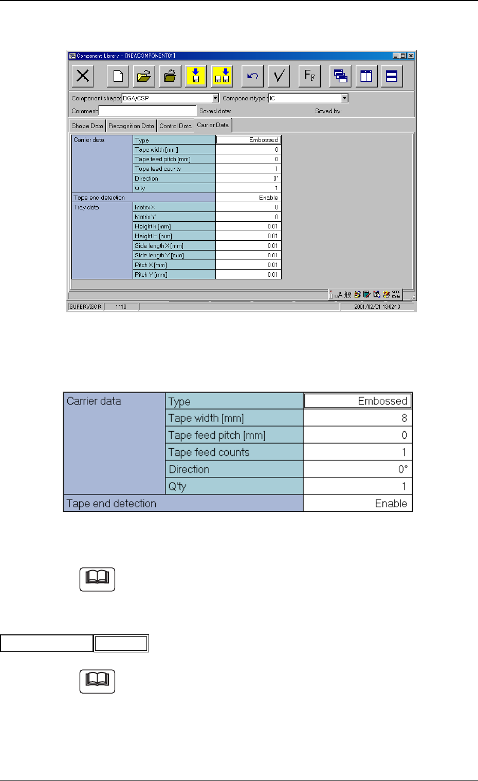
A03 Carrier Data
Fig. 22 Edit Window (Example)
(A03-01) Carrier Data
Fig. 23 Edit Window (Example)
Refer to the instruction manual "Component Library for TCM-X Series"
for details.
(A03-02) Tape end detection
Refer to the instruction manual "Component Library for TCM-X Series"
for details.
Tape end detection
Fig.24
Enable
Note
Note
0307-001 16 Tg0930-PM-SO
5.2 Parameters (A03-01), (A03-02)
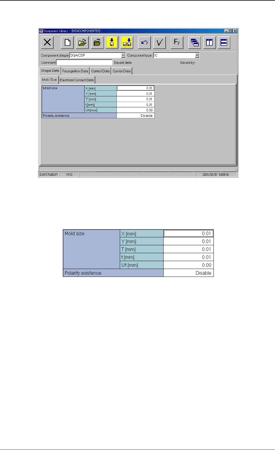
B01 Shape Data
Fig. 25 Edit Window (Example)
(B01-02) Mold size
Fig. 26 Edit Window (Example)
0307-001 17
Tg0930-PM-SO
5.2 Parameters (B01-02)
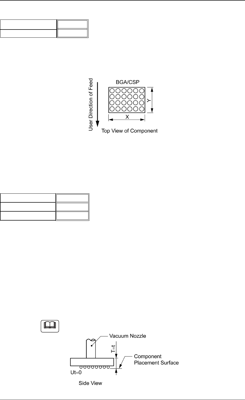
(1) X [mm] (Horizontal), Y [mm] (Vertical)
Set Dimensions X and Y of the molded section.
Unit: mm
Area Array
Fig. 28
Data Input Range:
X: 0.01 to 150.00
Y: 0.01 to 150.00
(2) T [mm] (thickness), t [mm] (thickness), and Ut [mm] (thickness)
Set the thickness of the component.
T [mm] (thickness) : Thickness between Component Place-
ment and Uppermost Surfaces
t [mm] (thickness) : Thickness between Component Place-
ment and Nozzle Pickup Surfaces
Ut [mm] (thickness) : Thickness between Component Lower-
most and Placement Surfaces
Unit: mm
Data Input Range: 0 to 9.99
Example of "T = t"
Fig. 30
Fig.27
X [mm] (Horizontal)
Y [mm] (Vertical)
3.30 [mm]
3.30 [mm]
0307-001 18 Tg0930-PM-SO
Note
5.2 Parameters (B01-02)
5.70 [mm]
5.70 [mm]
0.00 [mm]
T [mm] (thickness)
t [mm] (thickness)
Ut [mm] (thickness)
Fig.29