SOM-1735-001.pdf - 第22页
(B01-12) Electrode T ype Dat a Set the shape, the dimension, etc., of the electrode. Fig. 40 (1) Shape Set the shape of the electrode. Only "Round" can be selected at present. (2) Dim 1 [mm] Set the diameter of…
(3) # Of types
Set the number of electrode types.
Data Input Range: 1 to 3
When several types are specified, it becomes possible to handle such
components that have electrodes of different diameters.
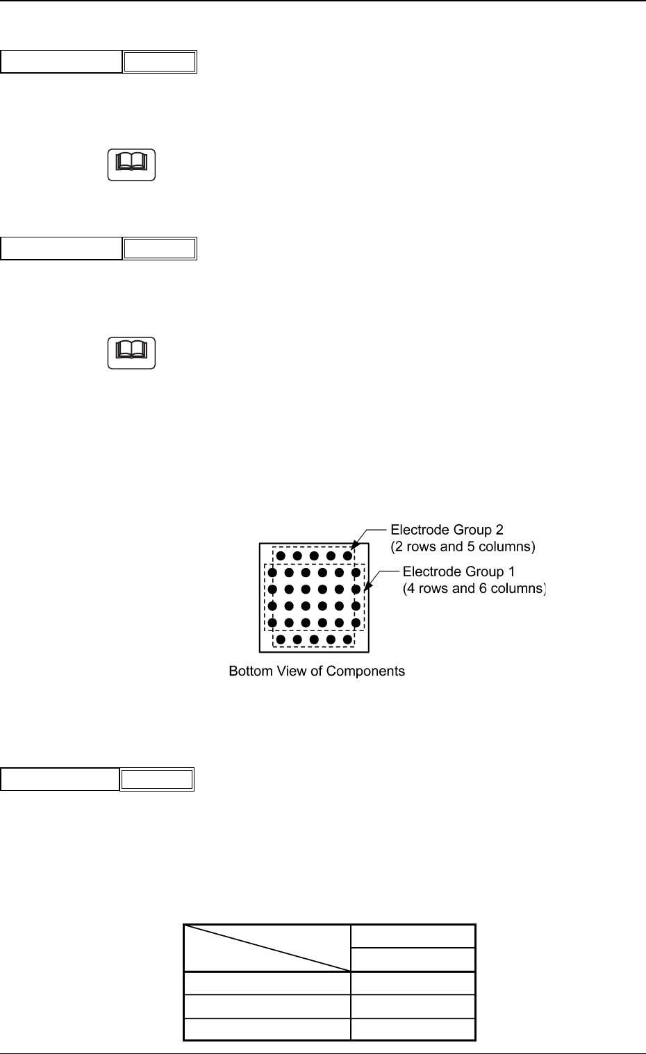
(4) # Of groups
Set the number of electrode groups.
Data Input Range: 1 to 6
When the formation of a special BGA cannot be expressed by a certain
array type, such a BGA component can be used by increasing the num-
ber of electrode groups.
Groups can be overlapped with each other.
Example: The electrodes arrayed in the 1st and 6th rows are shifted
by half a pitch, compared with the electrodes in the 2nd
through 5th rows.
Fig. 38
(5) Extended setting
Select "Enable" or "Disable" to determine whether or not the extended
data should be used.
When "Enable" is set in the "Extended setting" text box, the extended
data such as information on missing electrodes can be specified.
The following shows the extended data that can be specified.
Table 9
Area Array
BGA/CSP
# of Types
# of Groups
Missing Elctd Set
Fig.36
# Of types
1
Fig.37
# Of groups
1
5.2 Parameters (B01-11)
Note
Note
Fig.39
Extended setting Enable
0307-001 20 Tg0930-PM-SO
(B01-12) Electrode Type Data
Set the shape, the dimension, etc., of the electrode.
Fig. 40
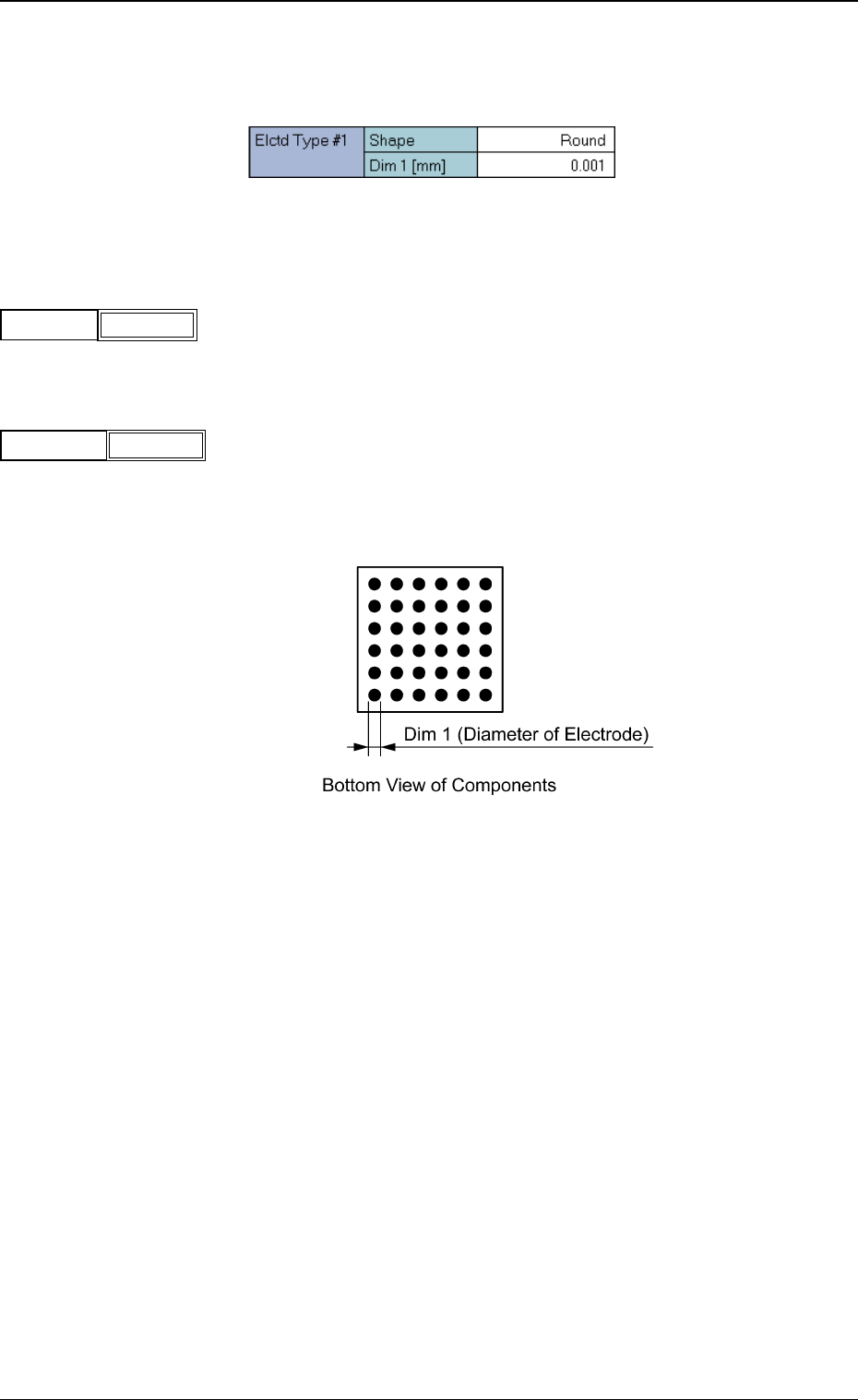
(1) Shape
Set the shape of the electrode.
Only "Round" can be selected at present.
(2) Dim 1 [mm]
Set the diameter of the electrode.
Unit: mm
Data Input Range: 0.001 to 9.999
Fig. 43
Fig.42
Dim 1 [mm]
0.001
Fig.41
Shape
Round
0307-001 21 Tg0930-PM-SO
5.2 Parameters (B01-12)
(B01-13) Electrode Group Data
The following parameters can be specified to classify some electrodes
into a group(s).
Fig. 44
(1) Type No.
Set the electrode type data No. related to the specified group.
Unit: Type
Data Input Range: 1 to 3
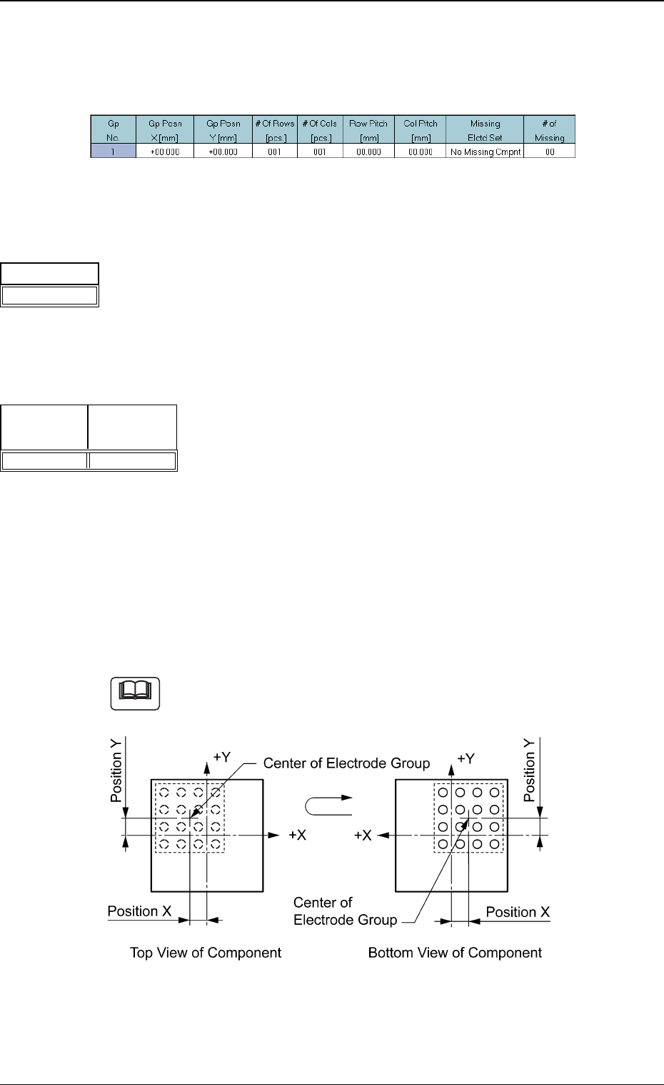
(2) Gp Posn X [mm], Y [mm]
Set the center position of the electrode group based on the center of
the mold.
Unit: mm
Data Input Range:
X: -99.999 to +99.999
Y: -99.999 to +99.999
As the center of the electrode group is located at the center of the mold in
normal cases, the coordinates X and Y become "0" (zero). (X, Y = 0,0)
Fig. 47
Fig.45
Type No.
1
Note
0307-001 22 Tg0930-PM-SO
5.2 Parameters (B01-13)
Fig.46
Gp Posn
X [mm]
+00.000
Gp Posn
Y [mm]
+00.000