SOM-1735-001.pdf - 第26页
(B01-14) Missing Electrode Dat a Set the missing electrode data. Fig. 55 (1) Missing Stg Row , Missing Stg Col Set the row and column Nos. from which the missing electrode block sta rt s. Dat a Input Range: 1 to 255 (2) …
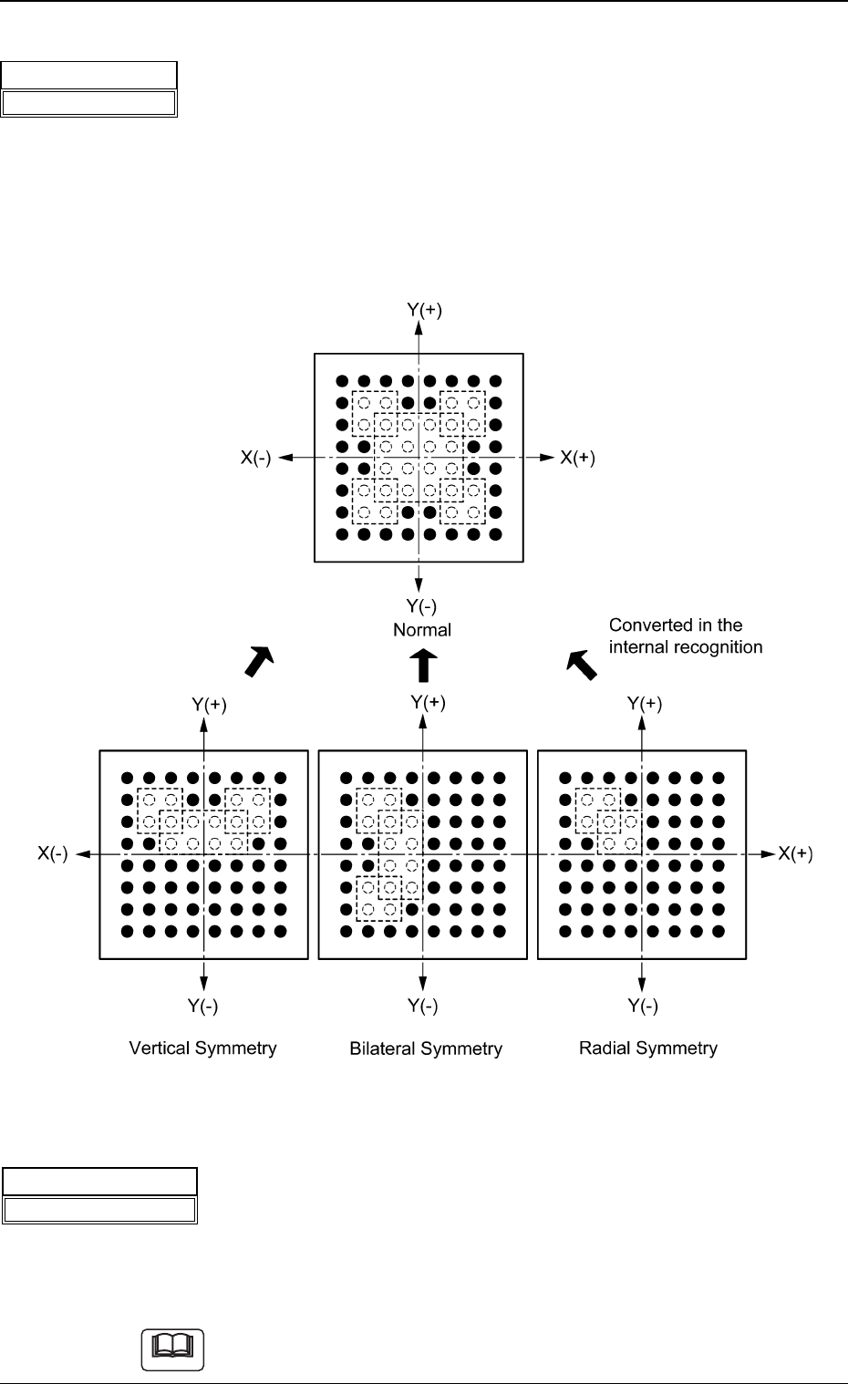
(5) Missing Elctd Set
Select one of the following options to determine how symmetrically
the electrodes are missing.
No Missing Cmpnt Normal Vertical Symmetry
Bilateral Symmetry Radial Symmetry
The selection of an option will simplify the designation of the missing
blocks.
Fig. 53
(6) # of Missing Blocks
Set the number of missing blocks.
When some electrodes are missing in the arrayed ones, the group of
electrodes is regarded as a block (a group of missing electrodes) and
the number of blocks can be specified.
Data Input Range: 1 to 40
Part of blocks can be overlapped with each other.
5.2 Parameters (B01-13)
Fig.52
Missing Elctd Set
No Missing Cmpnt
Note
Fig.54
# of Missing Blocks
01
0307-001 24 Tg0930-PM-SO
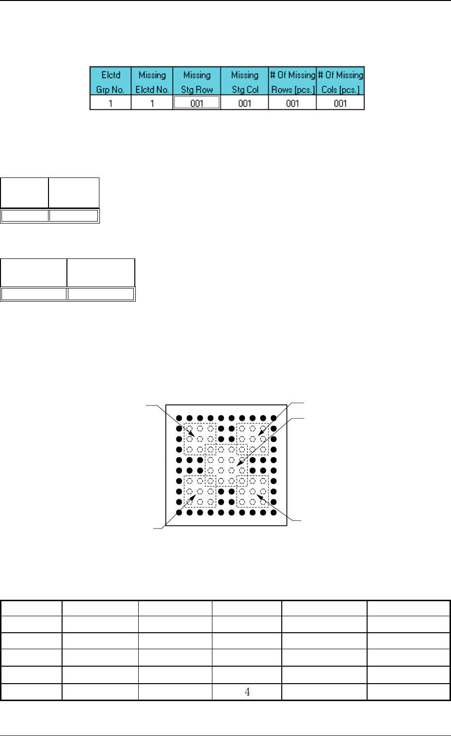
(B01-14) Missing Electrode Data
Set the missing electrode data.
Fig. 55
(1) Missing Stg Row, Missing Stg Col
Set the row and column Nos. from which the missing electrode block
starts.
Data Input Range: 1 to 255
(2) # Of Missing Rows [pcs.], # Of Missing Cols [pcs.]
Set the number of missing rows and columns.
Data Input Range: 1 to 255
Example:
Fig. 58
Table 10
0307-001 25 Tg0930-PM-SO
Top View of Component
Column
Missing Block 1
Missing Block 2
Missing Block 4
Missing Block 5
Missing Block 3
Row
1 2 3 4 5 6 7 8 9 10
1
2
3
4
5
6
7
8
9
10
Elctd Grp No.
1
1
1
1
1
Missing Elctd No.
1
2
3
4
5
Missing Stg Row
2
7
7
2
4
Missing Stg Col
2
2
7
7
# Of Missing Rows [pcs.]
3
3
3
3
4
# Of Missing Cols [pcs.]
3
3
3
3
4
5.2 Parameters (B01-14)
Fig.56
Missing
Stg Col
001
Missing
Stg Row
001
Fig.57
# Of Missing
Rows [pcs.]
001
# Of Missing
Cols [pcs.]
001
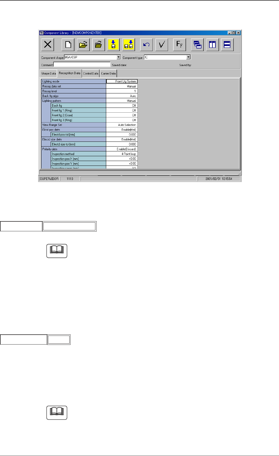
B02 Recognition Data
Fig. 59 Edit Window (Example)
(B02_01) Lighting mode
Set "Front Ltg System" to select a lighting mode.
When small components (smaller than size 2012) are recognized, use a
vacuum nozzle for front lighting recognition and dark image of whose
pick-up surface is photo-scanned.
When a vacuum nozzle for back lighting recognition is used to recognize
components other than small ones and a bright image of the nozzle’s
pick-up surface is photo-scanned, a recognition error might occur be-
cause the recognition is influenced by the vacuum nozzle.
(B02_02) Recog data set
Select one of the following options to specify whether the recognition
data related to each individual component shapes should be set au-
tomatically or manually.
Auto : The defaults (determined in advance) are automatically
set.
Manual : Each recognition data can be set manually.
Select "Auto" in normal cases.
Fig.61
Recog data set
5.2 Parameters (B02-01), (B02-02)
Fig.60
Front Ltg System
Lighting mode
Note
Note
0307-001 26 Tg0930-PM-SO
Manual