SOM-1735-001.pdf - 第41页
6.4 Specifications of Packaging Refer to the instruction manual "Component Library for TCM-X Series" for details. Specifications of Packaging for Component s with 8 or more Leads • Applicable Packaging T ypes P…
6. Standards of Component Library Naming
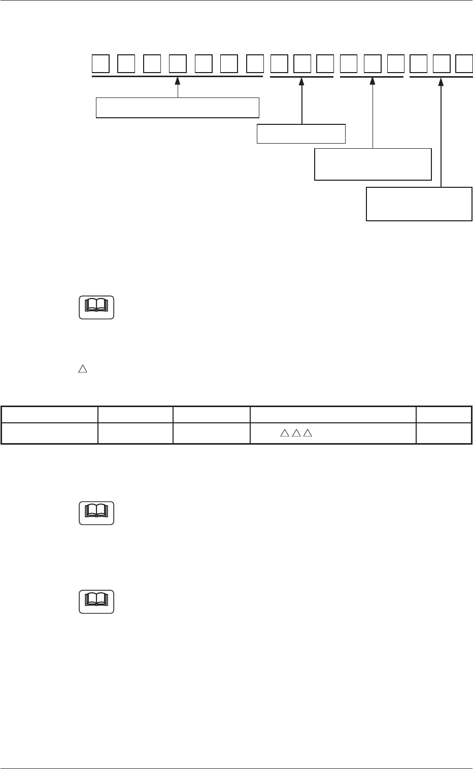
Component ID:
Fig. 94
6.1 Component Type, Size, Shape, and Characteristics
Refer to the instruction manual "Component Library for TCM-X
Series" for details.
List of Abbreviated Component Names
……………………………… Number of Electrodes
Table 12
Component Type Abbreviation Part Name Component ID (First 7 Digits) Remarks
IC BGA BGA-Type IC BGA
−
6.2 Serial Nos.
Refer to the instruction manual "Component Library for TCM-X
Series" for details.
6.3 Abbreviation of Component Maker
Refer to the instruction manual "Component Library for TCM-X
Series" for details.
16
6.1 Component Name, Size, etc.
6.2 Serial number
6.3 Abbreviation of
Component Maker
6.4 Specifications of
Packaging
151413121110987654321
Note
Note
Note
6. Standards of Component Library Naming
0307-001 39 Tg0930-PM-SO
6.4 Specifications of Packaging
Refer to the instruction manual "Component Library for TCM-X
Series" for details.
Specifications of Packaging for Components with 8 or more Leads
• Applicable Packaging Types
Paper, Embossed, Adhesive, and Bulk Tapes
• Applicable Components
ICs with 8 or more leads
Refer to the following table.
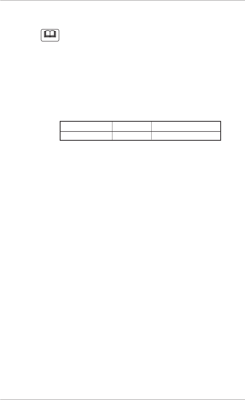
Table 13
Component Type Abbreviation Part Name
IC BGA Ball Grid Array-Type IC
6.4 Specifications of Packaging
Note
0307-001 40 Tg0930-PM-SO
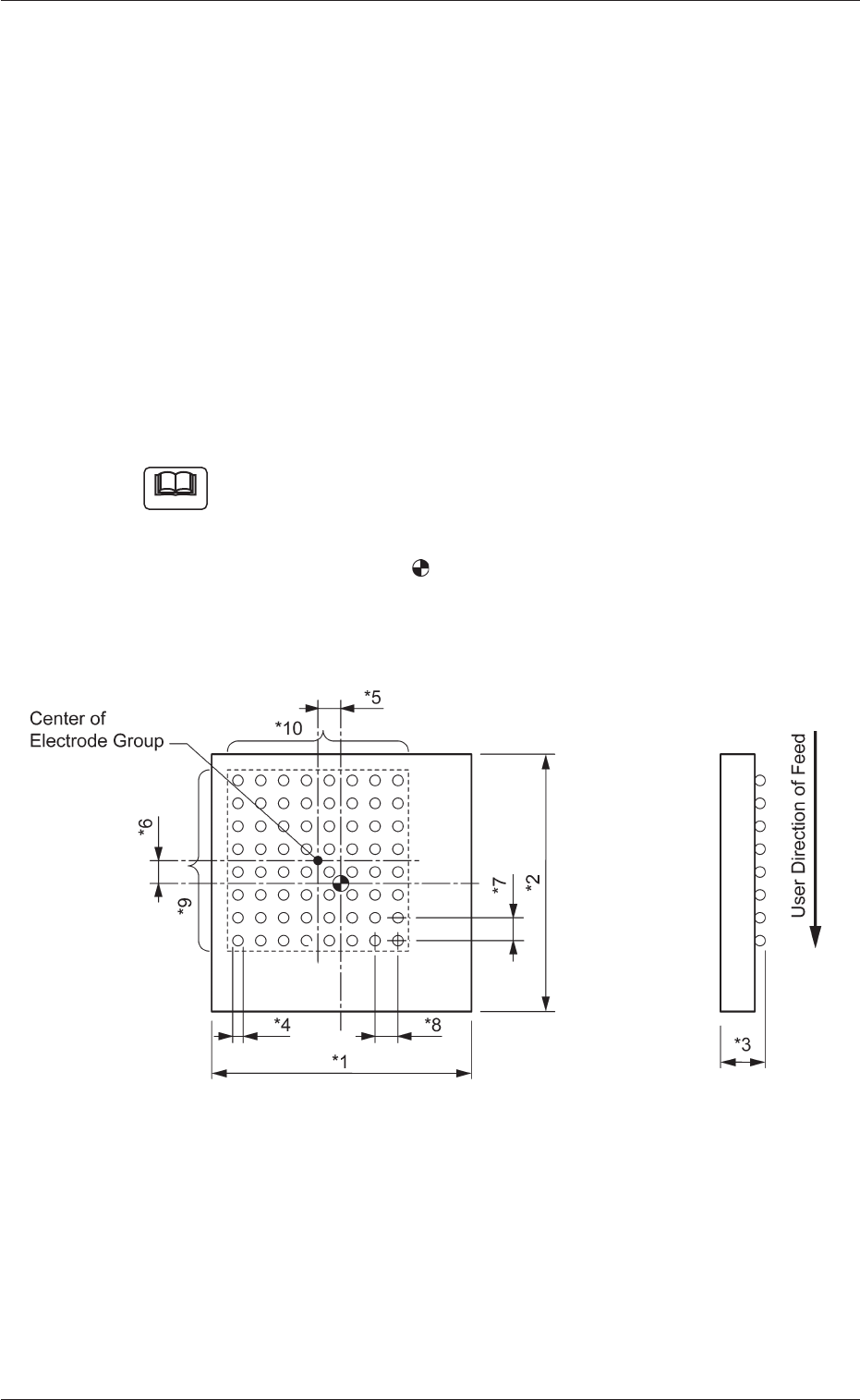
7. Measurement of Component Dimensions
Measure the dimensions (*1 through *10) in the figure below.
When a component has several electrode groups, set "Enable" in the
"Extended setting" text box and measure the dimensions (*5 through
*10) for Electrode Groups 2 through 6.
As for components with missing electrodes, set "Enable" in the "Ex-
tended setting" text box and the number of missing blocks in the "# of
Missing Electrodes" text box. After that, measure the dimensions (*11
through *14) in the figure.
When there are several missing blocks, measure the dimensions (*11
through *14) for Missing Electrodes 2, 3, and so on.
(Up to 40 blocks can be specified as electrode-missing blocks.)
(a) The figure shows the top view (ball-missing side) of the
component and is an example of "# of Electrode Groups
= 1".
(b) The center of the
mark is the reference point of the
component.
(In normal cases, the reference point is located at the
center of the mold.)
Fig. 95
7. Measurement of Component Dimensions
Note
0307-001 41 Tg0930-PM-SO