SOM-1735-001.pdf - 第28页
(B02_03) Recog level Set a recognition level for component checking. Set "1" in normal cases. Data Input Range: 1 to 99 When "2" or a larger number is set, "Manual" should be selected in the…
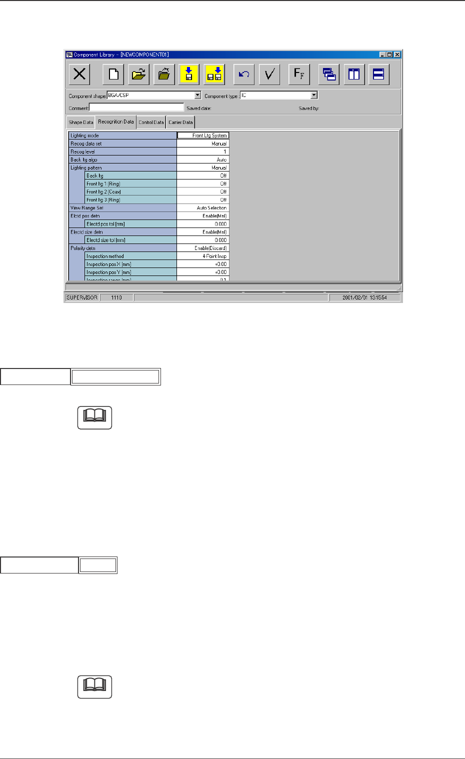
B02 Recognition Data
Fig. 59 Edit Window (Example)
(B02_01) Lighting mode
Set "Front Ltg System" to select a lighting mode.
When small components (smaller than size 2012) are recognized, use a
vacuum nozzle for front lighting recognition and dark image of whose
pick-up surface is photo-scanned.
When a vacuum nozzle for back lighting recognition is used to recognize
components other than small ones and a bright image of the nozzle’s
pick-up surface is photo-scanned, a recognition error might occur be-
cause the recognition is influenced by the vacuum nozzle.
(B02_02) Recog data set
Select one of the following options to specify whether the recognition
data related to each individual component shapes should be set au-
tomatically or manually.
Auto : The defaults (determined in advance) are automatically
set.
Manual : Each recognition data can be set manually.
Select "Auto" in normal cases.
Fig.61
Recog data set
5.2 Parameters (B02-01), (B02-02)
Fig.60
Front Ltg System
Lighting mode
Note
Note
0307-001 26 Tg0930-PM-SO
Manual
(B02_03) Recog level
Set a recognition level for component checking.
Set "1" in normal cases.
Data Input Range: 1 to 99
When "2" or a larger number is set, "Manual" should be selected in the
"Recog data set" text box.
(B02-04) Front ltg algo
Set a recognition system.
Select "BGA".
Auto: Each condition of the component data is considered and one
of the shadowed recognition systems in the table is selected.
Grid Pattern: The electrodes consisting of meshes (grids), the
bumps, etc., can be detected.
: Options representing the recognition systems
Be sure to select either one of the options.
: Options (Recognition Systems) to be selected when
"Auto" is set
Either one of the options is selected.
Table 11
Recognition System
Grid Pattern
Component Type
Component Shape Lighting Mode
Area Array BGA/CSP Front Lighting
To set a parameter, select "Manual" in the "Recog data set" text
box.
Fig.62
1
Recog level
Note
Fig.63
Auto
Front ltg algo
Note
0307-001 27 Tg0930-PM-SO
5.2 Parameters (B02-03), (B02-04)
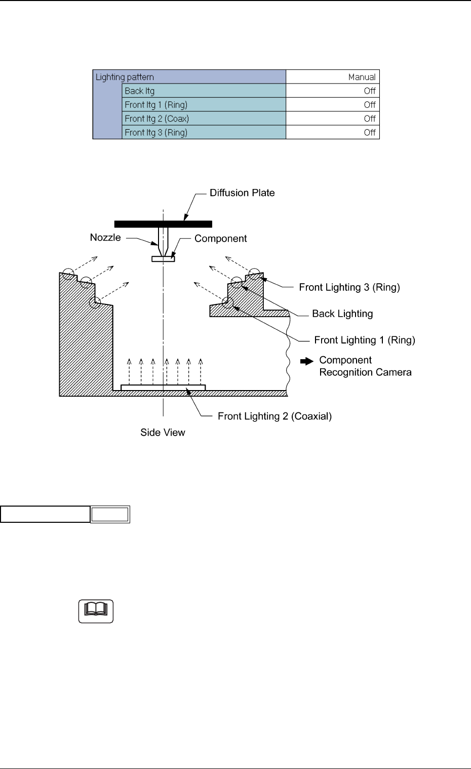
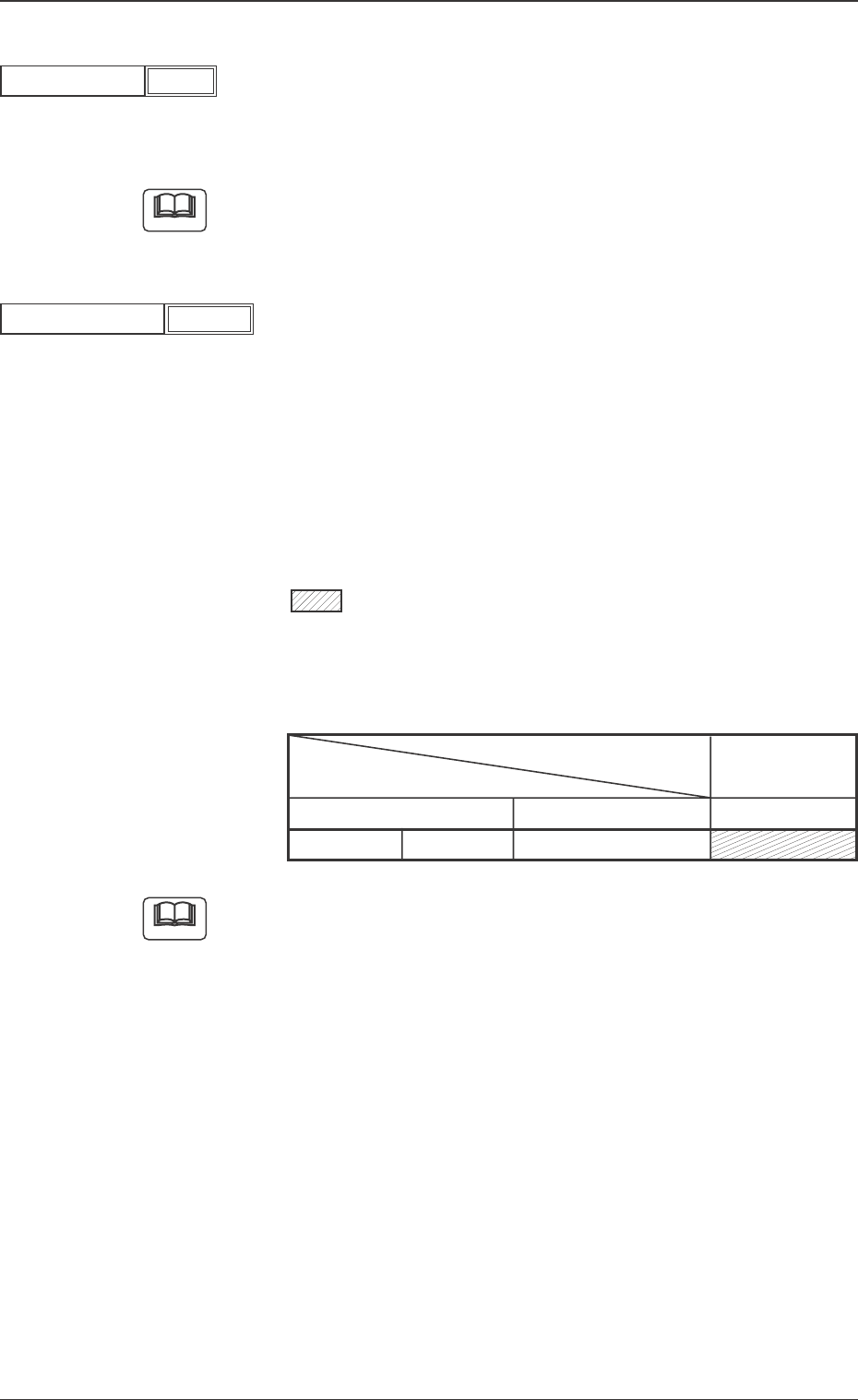
(B02-05) Lighting pattern
Set a lighting pattern to be used for component recognition.
Fig. 64 Edit Window (Example)
Fig. 65
(1) Lighting pattern
Select one of the following options to designate a lighting pattern.
Auto : The lighting patterns are automatically set for all lighting
units.
Manual : The lighting patterns can be set individually for each light-
ing unit.
(a) When the recognition cannot be made correctly due to improper light-
ing condition, set proper lighting patterns for the selected compo-
nent.
(b) To set a parameter, select "Manual" in the "Recog data set" text box.
Fig.66
Auto
Lighting pattern
Note
0307-001 28 Tg0930-PM-SO
5.2 Parameters (B02-05)