SOM-1735-001.pdf - 第43页
The figure shows the top view (electrode-missing side) of the component. Fig. 96 Individual Data Sheet (BGA/CSP) Minimum Unit: 0.001 mm *1 Mold size X [mm] *2 Mold size Y [mm] *3 Mold size t [mm] (thickness) [T [mm] (thi…
7. Measurement of Component Dimensions
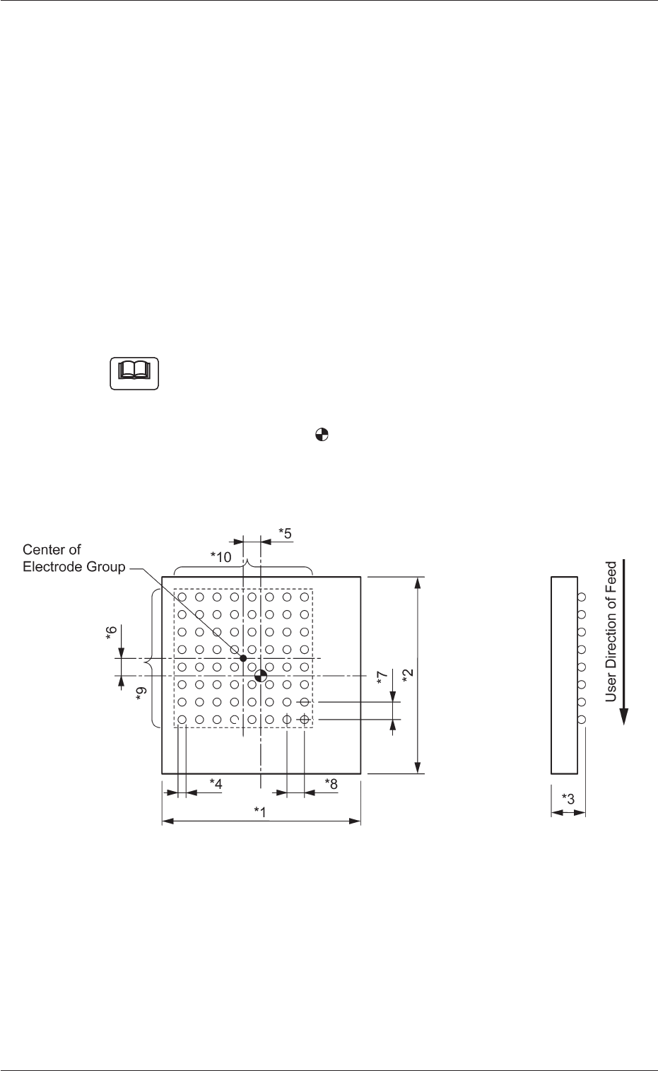
Measure the dimensions (*1 through *10) in the figure below.
When a component has several electrode groups, set "Enable" in the
"Extended setting" text box and measure the dimensions (*5 through
*10) for Electrode Groups 2 through 6.
As for components with missing electrodes, set "Enable" in the "Ex-
tended setting" text box and the number of missing blocks in the "# of
Missing Electrodes" text box. After that, measure the dimensions (*11
through *14) in the figure.
When there are several missing blocks, measure the dimensions (*11
through *14) for Missing Electrodes 2, 3, and so on.
(Up to 40 blocks can be specified as electrode-missing blocks.)
(a) The figure shows the top view (ball-missing side) of the
component and is an example of "# of Electrode Groups
= 1".
(b) The center of the
mark is the reference point of the
component.
(In normal cases, the reference point is located at the
center of the mold.)
Fig. 95
7. Measurement of Component Dimensions
Note
0307-001 41 Tg0930-PM-SO
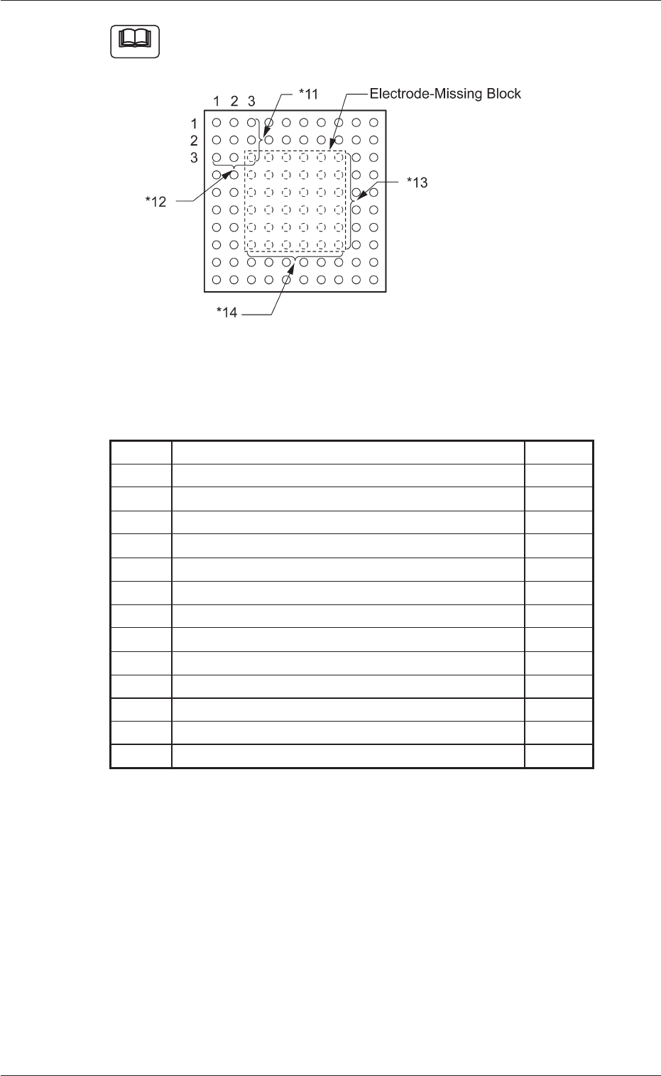
The figure shows the top view (electrode-missing side) of the
component.
Fig. 96
Individual Data Sheet (BGA/CSP)
Minimum Unit: 0.001 mm
*1 Mold size X [mm]
*2 Mold size Y [mm]
*3 Mold size t [mm] (thickness) [T [mm] (thickness)]
*4 Elctd Type #1 Dim 1 [mm]
*5 Gp Posn X [mm] of Gp No. 1
*6 Gp Posn Y [mm] of Gp No. 1
*7 Row Pitch [mm] of Gp No. 1
*8 Col Pitch [mm] of Gp No. 1
*9 # Of Rows [pcs.] of Gp No. 1
*10 # Of Cols [pcs.] of Gp No. 1
*11 Missing Stg Row of Elctd Grp No. 1
*12 Missing Stg Col of Elctd Grp No. 1
*13 # Of Missing Rows [pcs.] of Elctd Grp No. 1
*14 # Of Missing Cols [pcs.] of Elctd Grp No. 1
0307-001 42 Tg0930-PM-SO
7. Measurement of Component Dimensions
Note
8. "UNIT ADJ." Window (Submenu)
• Window Layout
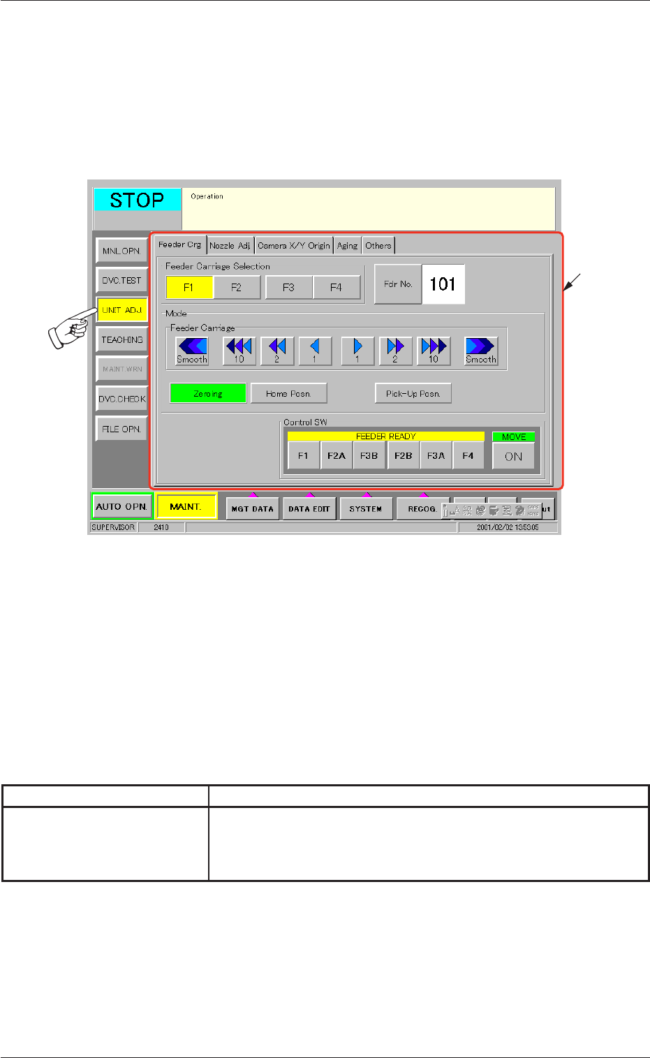
When the [UNIT ADJ.] button on the submenu bar is pressed, the fol-
lowing window opens. (Operation Sequence: [MAINT.] Button Æ [UNIT
ADJ.] Button on Submenu Bar Æ "UNIT ADJ." Window)
Fig. 97 "UNIT ADJ." Window (Submenu)
• Window Composition
*1 Tabs and Tab Sheets
The "UNIT ADJ." window (submenu) is provided with 5 tab
sheets. When each tab is pressed, the corresponding tab sheet
appears inside the window.
Table 14
Tab Description
Camera X/Y Origin This tab sheet enables the operator to perform the origin adjust-
ment of the image camera, the sensitivity adjustment of the CCD
camera, the intensity adjustment of front lighting, etc.
8. "UNIT ADJ." Window (Submenu)
0307-001 43 Tg0930-PM-SO
*1