SOM-1735-001.pdf - 第33页
0307-001 32 Tg0930-PM-SO (B02-14) Polarity detn S pecify how to determine the polarity (direction) of the component. Fig. 74 Edit Window (Example) (1) Polarity detn Set a parameter to specify whether or not the polarity …
(2) Electd pos tol [mm]
Set the tolerance value for the electrode position.
Unit: mm
Data Input Range: 0 to 9.999
To specify a parameter, "Manual" must be set in the "Recog
data set" text box and "Enable (Mnl)" in the "Elctd pos detn" text
box (described in (1)).
(3) Electd size detn
Select an option to specify whether or not the electrode size should
be determined.
Select one of the following options.
Disable Enable (Auto) Enable (Mnl)
Disable : Select this when the electrode size determination
should not be made.
Enable (Auto) : Select this to make the electrode size determina-
tion.
The automatically specified default is used as an
electrode size tolerance.
Enable (Mnl) : Select this to make the electrode size determina-
tion.
The arbitrarily specified value is used as an elec-
trode size tolerance.
To set a parameter, select "Manual" in the "Recog data set" text box.
(4) Electd size tol [mm]
Set the tolerance value for the electrode size.
Unit: mm
Data Input Range: 0 to 9.999
To specify a parameter, "Manual" must be set in the "Recog
data set" text box and "Enable (Mnl)" in the "Elctd size detn"
text box (described in (1)).
Note
Electd size tol [mm]
0.000
Enable (Auto)
Electd size detn
Fig.73
Note
0307-001 31 Tg0930-PM-SO
5.2 Parameters (B02-13)
Note
0307-001 32 Tg0930-PM-SO
(B02-14) Polarity detn
Specify how to determine the polarity (direction) of the component.
Fig. 74 Edit Window (Example)
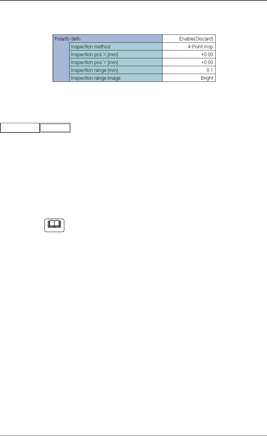
(1) Polarity detn
Set a parameter to specify whether or not the polarity determination
should be made.
Disable : Select this when the polarity determination
should not be made.
Enable (Discard) : When the polarity is checked and determined
as a different one, a recognition error occurs.
Enable (Placement) : After the polarity is checked and determined,
the component is placed according to the de-
termined polarity.
(a) When "Enable (Placement)" is selected, the recognition processing
time becomes twice or more as long as the normal one.
(b) When it is required to check whether or not a component has a po-
larity (when components are not fed in the specified direction), "En-
able (Discard)" or "Enable (Placement)" must be set in the text box.
The machine performs the recognition operation after checking the
polarity.
(c) The following requirements must be met when "Enable (Discard)" or
"Enable (Placement)" is selected.
• The average gray value in the inspection range of the polarity
mark must be 20 shades of gray or more, compared with the other
inspection ranges.
(The gray value in the inspection range can be checked through
the component recognition test.)
5.2 Parameters (B02-14)
Fig.75
Polarity detn
Disable
Note
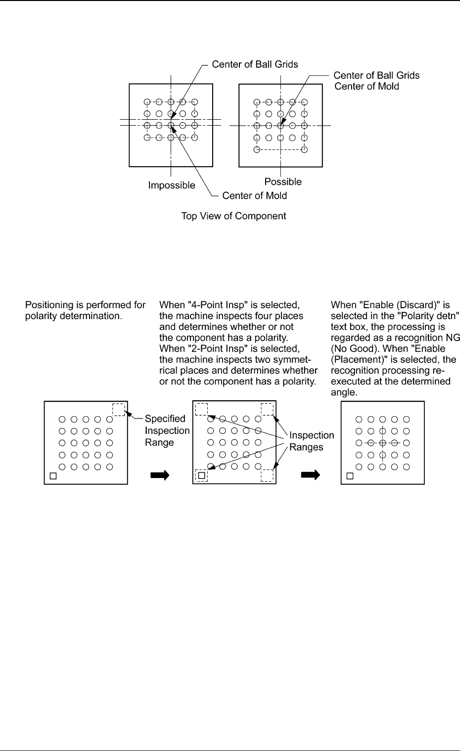
• In the case of "BGA", the center of the ball grids must be aligned
with the center of the mold.
Fig. 76
Sequence of Polarity Determination
Top View of Component
(Polarity Different by 180°)
Fig. 77
0307-001 33 Tg0930-PM-SO
5.2 Parameters (B02-14)