SOM-1735-001.pdf - 第30页
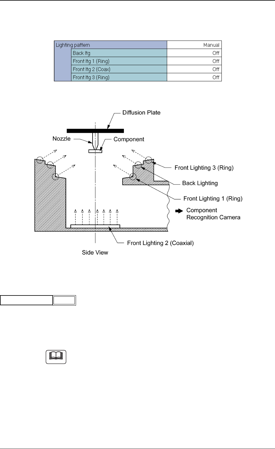
(2) Back Ltg When "Manual" is set in the "Lighting pattern" text box, specify a light- ing pattern for the back lighting recognition system. Select "On" or "Off". (3) Front ltg 1 (…
(B02-05) Lighting pattern
Set a lighting pattern to be used for component recognition.
Fig. 64 Edit Window (Example)
Fig. 65
(1) Lighting pattern
Select one of the following options to designate a lighting pattern.
Auto : The lighting patterns are automatically set for all lighting
units.
Manual : The lighting patterns can be set individually for each light-
ing unit.
(a) When the recognition cannot be made correctly due to improper light-
ing condition, set proper lighting patterns for the selected compo-
nent.
(b) To set a parameter, select "Manual" in the "Recog data set" text box.
Fig.66
Auto
Lighting pattern
Note
0307-001 28 Tg0930-PM-SO
5.2 Parameters (B02-05)
(2) Back Ltg
When "Manual" is set in the "Lighting pattern" text box, specify a light-
ing pattern for the back lighting recognition system.
Select "On" or "Off".
(3) Front ltg 1 (Ring)
When "Manual" is selected in the "Lighting pattern" text box, specify a
lighting pattern of the ring lighting for the front lighting system located
at the lower side.
Select "On" or "Off"
(4) Front ltg 2 (Coaxial)
When "Manual" is selected in the "Lighting pattern" text box, specify a
lighting pattern of the coaxial lighting for the front lighting system.
Select "On" or "Off"
(5) Front ltg 3 (Ring)
When "Manual" is selected in the "Lighting pattern" text box, specify a
lighting pattern of the ring lighting (used mainly for BGA components)
for the front lighting system located at the upper side.
Select "On" or "Off"
Fig.69
Off
Front ltg 2 (Coaxial)
Fig.67
Off
Back Ltg
Fig.68
Off
Front ltg 1 (Ring)
5.2 Parameters (B02-05)
Fig.70
Off
Front ltg 3 (Ring)
0307-001 29 Tg0930-PM-SO
(B02-06) View Range Set
Set a view size to be used for recognition.
Select one of the following options.
Auto Selection Small View Large View
Auto Selection : "Large View" or "Small View" can be selected
automatically according to the selected com-
ponent.
Small View : Select this to use the small view (movable cam-
era).
Large View : Select this to use the large view (fixed cam-
era).
In normal cases, select "Auto Selection".
To set a parameter, select "Manual" in the "Recog data set" text box.
(B02-13) Electrode Recognition Data
(1) Electrode Position Determination
Select an option to specify whether or not the electrode position should
be determined.
Select one of the following options.
Disable Enable (Auto) Enable (Mnl)
Disable : Select this when the electrode position determi-
nation should not be made.
Enable (Auto) : Select this to make the electrode position deter-
mination.
The automatically specified default is used as an
electrode position tolerance.
Enable (Mnl) : Select this to make the electrode position deter-
mination.
The arbitrarily specified value is used as an elec-
trode position tolerance.
To set a parameter, select "Manual" in the "Recog data set" text
box.
5.2 Parameters (B02-06), (B02-013)
Fig.71
Auto Selection
View Range Set
Note
Note
0307-001 30 Tg0930-PM-SO
Electd pos tol [mm]
0.000
Enable (Auto)
Elctd pos detn
Fig.72