SOM-1735-001.pdf - 第19页
(1) X [mm] (Horizontal), Y [mm] (V ertical) Set Dimensions X and Y of the molded section. Unit: mm Area Array Fig. 28 Dat a Input Range: X: 0.01 to 150.00 Y : 0.01 to 150.00 (2) T [mm] (thickness), t [mm] (thickness), an…
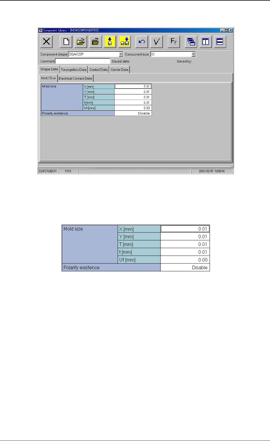
B01 Shape Data
Fig. 25 Edit Window (Example)
(B01-02) Mold size
Fig. 26 Edit Window (Example)
0307-001 17
Tg0930-PM-SO
5.2 Parameters (B01-02)
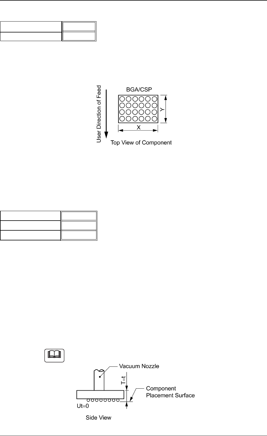
(1) X [mm] (Horizontal), Y [mm] (Vertical)
Set Dimensions X and Y of the molded section.
Unit: mm
Area Array
Fig. 28
Data Input Range:
X: 0.01 to 150.00
Y: 0.01 to 150.00
(2) T [mm] (thickness), t [mm] (thickness), and Ut [mm] (thickness)
Set the thickness of the component.
T [mm] (thickness) : Thickness between Component Place-
ment and Uppermost Surfaces
t [mm] (thickness) : Thickness between Component Place-
ment and Nozzle Pickup Surfaces
Ut [mm] (thickness) : Thickness between Component Lower-
most and Placement Surfaces
Unit: mm
Data Input Range: 0 to 9.99
Example of "T = t"
Fig. 30
Fig.27
X [mm] (Horizontal)
Y [mm] (Vertical)
3.30 [mm]
3.30 [mm]
0307-001 18 Tg0930-PM-SO
Note
5.2 Parameters (B01-02)
5.70 [mm]
5.70 [mm]
0.00 [mm]
T [mm] (thickness)
t [mm] (thickness)
Ut [mm] (thickness)
Fig.29
(B01-04) Polarity Existence
Set "Enable" or "Disable" to determine whether or not the component
has a polarity (direction).
This data is used for optimization of the pattern program.
Select "Enable" or "Disable".
Refer to the instruction manual "Optimization Software" for de-
tails.
(B01-11) Electrical Contact Data
Set the basic parameters related to the electrodes of the components.
Fig. 32
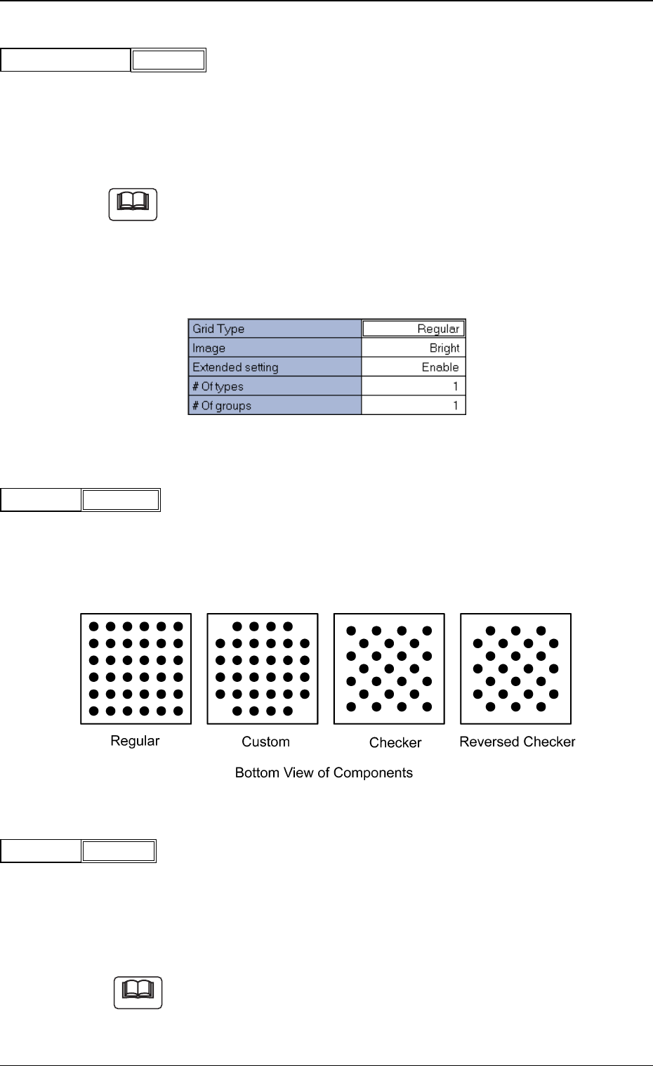
(1) Grid Type
Select one of the following grid types.
Regular : Regular Lattice
Custom : Lattice having no electrodes at 4 corners
Checker : Staggered Array
Reversed Checker : Reversed Staggered Array
Fig. 34
(2) Image
Select one of the following options depending on how the image of
the electrode is captured in comparison with the mold.
Bright : Select this when the captured image looks brighter than
the mold.
Dark : Select this when the captured image looks darker than
the mold.
(a) In normal cases, select "Bright".
(b) When the mold of a BGA component is made of ceramic, it might be
better to select "Dark".
Fig.35
Image Bright
Fig.33
Grid Type Regular
5.2 Parameters (B01-04), (B01-11)
Fig.31
Polarity Existence
Enable
Note
Note
0307-001 19 Tg0930-PM-SO