88192278-01-19 Installation Master.pdf - 第102页
SERVICES REQUIRED CENTRE OF GRAVITY AND S EISMIC ANCHORAGE 3.12 Installation Manual Chapter Issue 16, Nov 19
SERVICES REQUIRED
CENTRE OF GRAVITY AND SEISMIC ANCHORAGE
Chapter Issue 16, Nov 19 Installation Manual 3.11
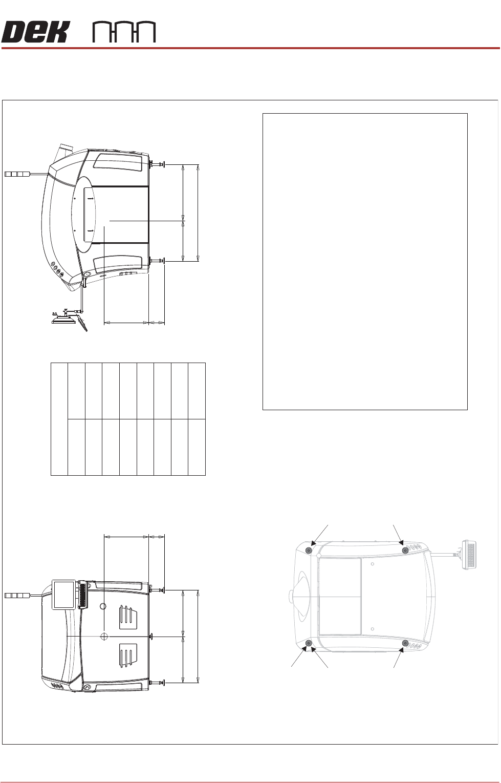
CENTRE OF GRAVITY AND SEISMIC ANCHORAGE
Figure 3-9 Type 1 Covers (Only)
Side View (right)
CG
L2
a
b
h
L1
Front View
CG
L3
d
b
h
c
Centre of Gravity
a
b
c
d
h
L1
L2
L3
1150mm
130mm
1106mm
530mm
485mm
565mm
665mm
541mm
Plan View
Centre of Gravity
Seismic Anchorage
Machine Feet
(in 4 positions
)
Min = -100kg
Max = +400kg
Min = -100kg
Max = +400kg
Min = -100kg
Max = +400kg
Min = -100kg
Max = +400kg
Seismic Anchorage
The calculations for the downward and upward force of the feet
is calculated in line with the 1997 Uniform Building Code and
SEMI S2-0703. Results indicate that under worse circumstances
(calculation for hazardous fluids
) an upward lifting force has to be
expected and it is strongly recommended to secure the machine
directly to the floor.
NOTE
In the figure on the left, negative numbers are upward loads and
positive numbers are downward loads.
Appropriate attachment points may be fitted to the front and rear
of the machine base frame. For more information, contact DEK
Printing Machines.
Alternatively, the supplied machine feet can be replaced with feet
incorporating holes allowing the feet to be secured directly to the floor.
Additional seismic calculations must be undertaken for the floor and
any anchor points that are used.
The length of the machine feet
(measurement
in the figures above
)
b
must not exceed 130mm to meet seismic anchorage calculations.

SERVICES REQUIRED
CENTRE OF GRAVITY AND SEISMIC ANCHORAGE
3.12 Installation Manual Chapter Issue 16, Nov 19

PRINTER PREPARATION
GENERAL
Chapter Issue 15, May 20 Installation Manual 4.1
CHAPTER 4 PRINTER PREPARATION
GENERAL Prior to printer power up it is essential to follow the preparation instructions in
this section thus ensuring correct operation of the printer and prevent any
possible damage occurring to the printer or personnel.
NOTE
Do not remove the red transit brackets, tie wraps or screws attached to the
printer until the printer has been moved to its designated position.
Using the Pack List, ensure that all items are supplied.
Visually inspect all printer components and equipment for completeness,
condition and damage. If any components or equipment are incomplete,
damaged or in poor condition, make a note of this on the Outstanding Issues
page found in the Installation Documentation chapter of this manual.
Transportation
WARNING
MACHINE LIFTING. TO PREVENT SERIOUS INJURY TO PERSONNEL, DURING
LIFTING AND TRANSPORTATION OPERATIONS, ENSURE THE MACHINE IS
LIFTED AND TRANSPORTED IN ACCORDANCE WITH INSTRUCTIONS DETAILED
IN THIS SECTION.
NOTE
Damage to the printer will occur if the printer is lifted:
• Using lifting strops
OR...
• From the sides
ASM recommends that the printer is lifted from the rear at all times however,
the printer may be lifted from the front if the printer is to be moved a short
distance or moved into line.
The printer may be lifted using a forklift truck or similar printer that meets the
following criteria:
• Minimum fork length of 1372mm (54 inches)
• Fork span >686mm (27 inches) and <914mm (36 inches)
• Fork Height (thickness) <50mm (2 inches)
• Lifting capability of 2000kg