88192278-01-19 Installation Master.pdf - 第134页
PRINTER PREPARATION PRINTER ASSEMBLY 4.32 Installation Manual Chapter Issue 15, May 20 MMI Assembly Fitting NOTE When fitting the MMI assembly to the printer , ensure that the cables are routed and secured so they do not…
PRINTER PREPARATION
PRINTER ASSEMBLY
Chapter Issue 15, May 20 Installation Manual 4.31
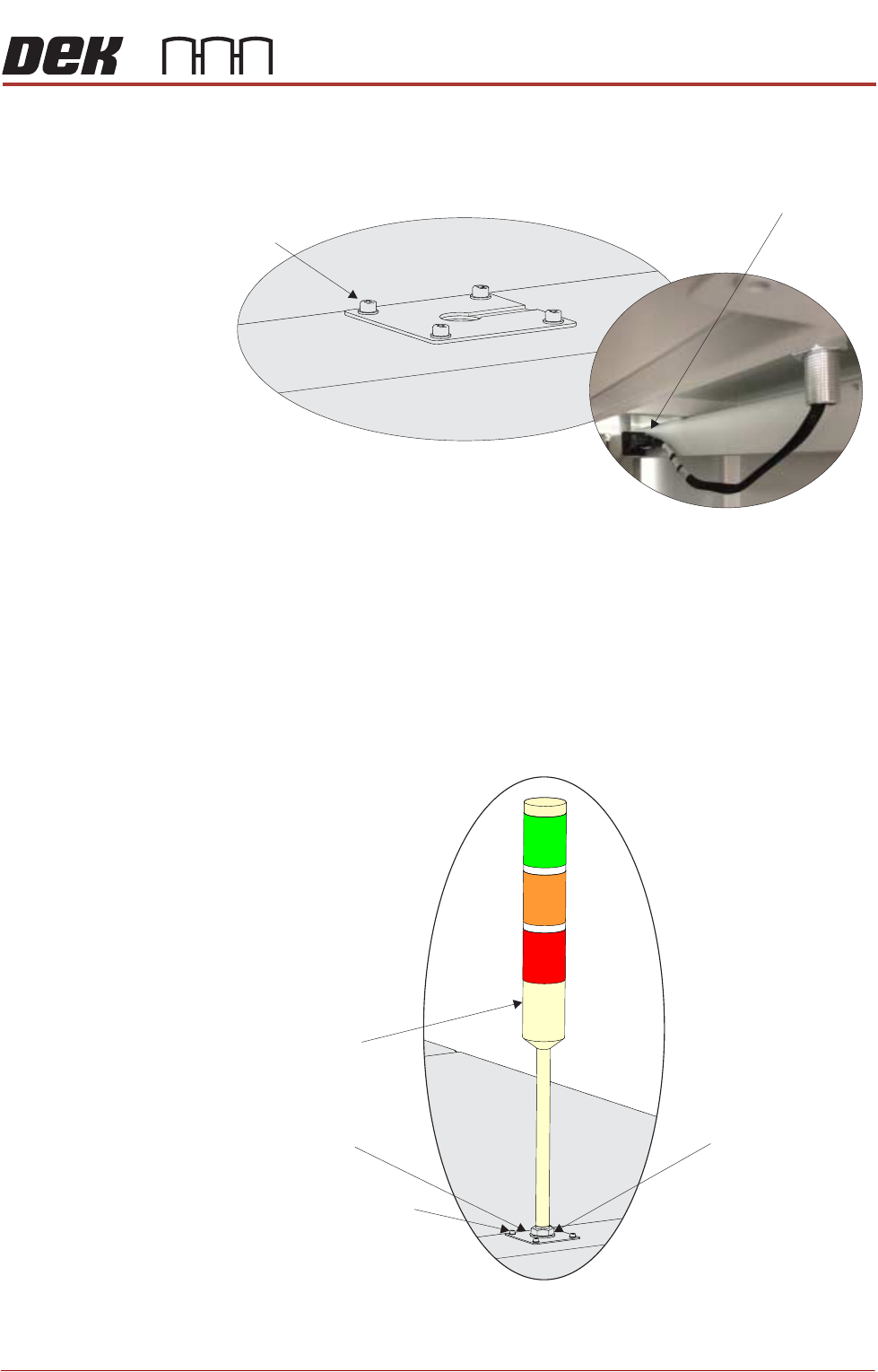
Type 5 Covers 1. Using a 3mm Allen key, remove the beacon bracket securing screws from
the printer cover.
2. Remove the Rear Corner Panel to reveal socket 14SK07.
3. Feed the tricolour beacon connection 14PL07 down through the hole in the
cover with any surplus cable.
4. Connect the tricolour beacon connection 14PL07 to 14SK07.
5. Fit the beacon bracket to the printer cover using the four beacon bracket
securing screws ensuring that any cables are not trapped between the
beacon bracket and the cover.
6. Secure the Rear Corner Panel into position.
Beacon Bracket
Securing Screws
(in 4 positions)
View on Underside of Beacon Bracket
Beacon Connector
()14SK07
View on Right Hand Side of the Machine
Tricolour Beacon
Beacon Securing Nut
Beacon Bracket Securing
Screws (in 4 positions)
Beacon Bracket
PRINTER PREPARATION
PRINTER ASSEMBLY
4.32 Installation Manual Chapter Issue 15, May 20
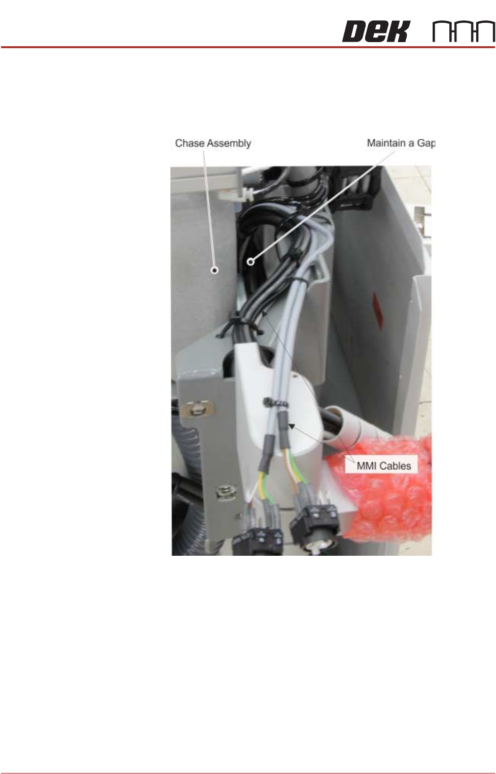
MMI Assembly Fitting
NOTE
When fitting the MMI assembly to the printer, ensure that the cables are routed
and secured so they do not foul on any of the printer’s moving parts e.g: the
chase assembly.
Use the following procedures to fit the monitor:
Type 1 Covers 1. Remove the front panel.
2. Locate the following cables stowed within the printer:
• Monitor Power Cable
•VGA Cable
• Touchscreen Cable (USB)
• USB Cable - Rear Monitor USB Connector
3. Feed the cables out of the printer and downwards through the hole of the
monitor arm support bracket
4. From the monitor arm, feed the IR Receiver cable upwards through the hole
of the monitor arm support bracket and into the printer.
PRINTER PREPARATION
PRINTER ASSEMBLY
Chapter Issue 15, May 20 Installation Manual 4.33
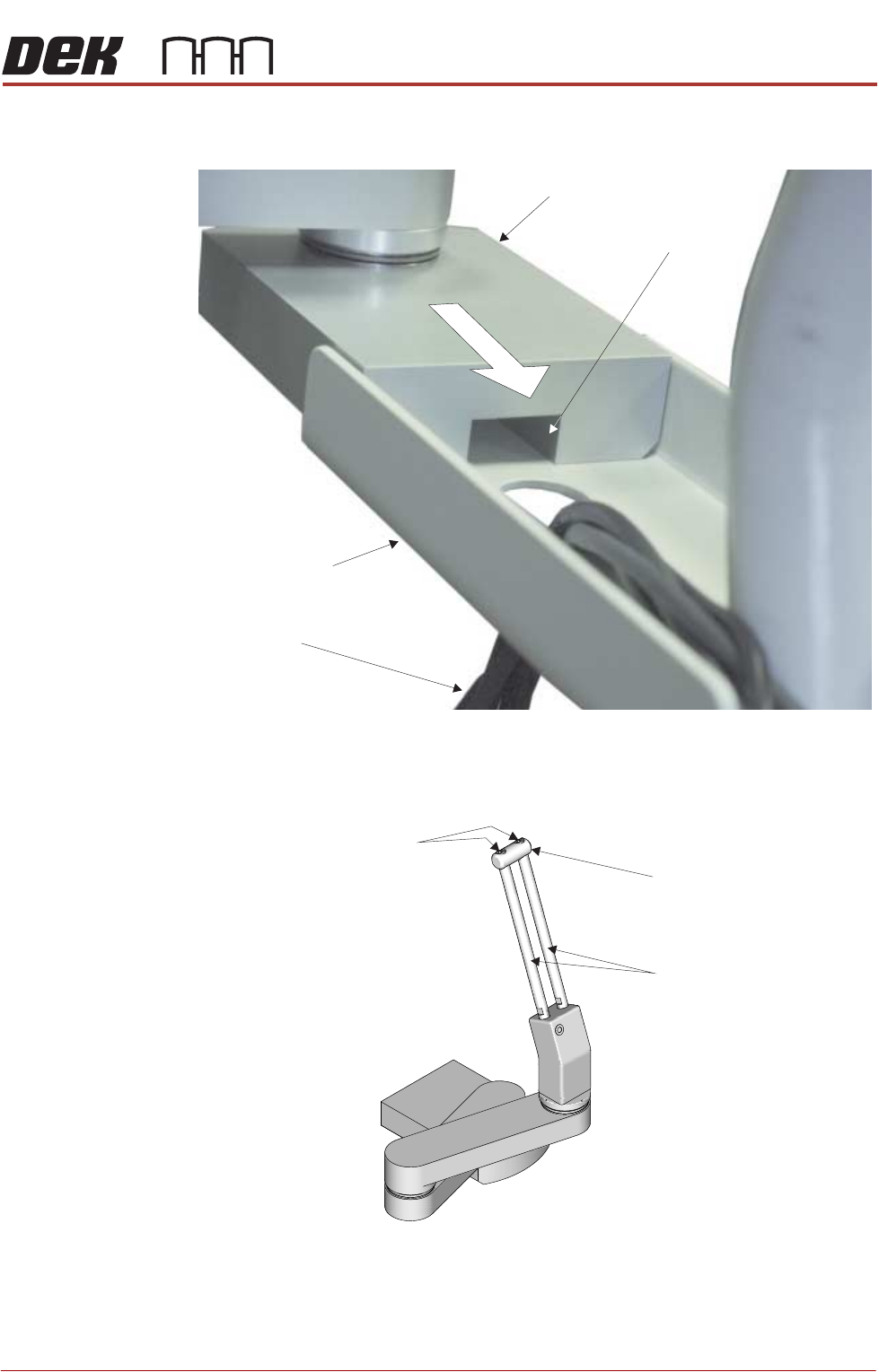
5. Fit the monitor arm to the monitor bracket ensuring that no cables are
trapped between the arm and bracket.
6. Secure the monitor arm to the bracket with three screws from below.
7. Using a 2.5mm Allen key, remove the end block from the top of the
adjustment bars.
8. Slide the monitor bracket on to the adjustment bars and tighten the locking
thumbscrew.
9. Refit the end block.
10. Fit the monitor to the monitor fixing bracket ensuring that all four studs are
Monitor Support Arm
MMI Cable Channel
MMI Cables
Monitor Support
Arm Bracket
Securing Screws
End Block
Adjustment Bars