88192278-01-19 Installation Master.pdf - 第24页
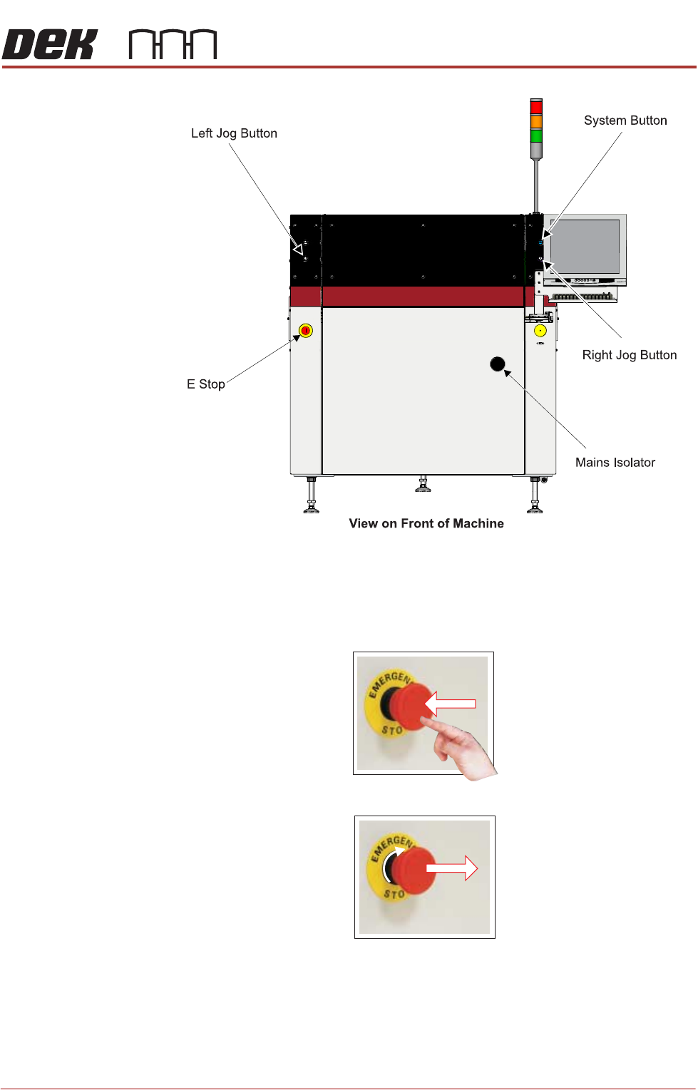
SAFETY FEATURES GENERAL 1.12 Installation Manual Chapter Issue 15, Nov 19 Figure 1-4 T ype 4 View on Front of Machine Left Jog Button E Stop System Button Mains Isolator
SAFETY FEATURES
GENERAL
Chapter Issue 15, Nov 19 Installation Manual 1.11
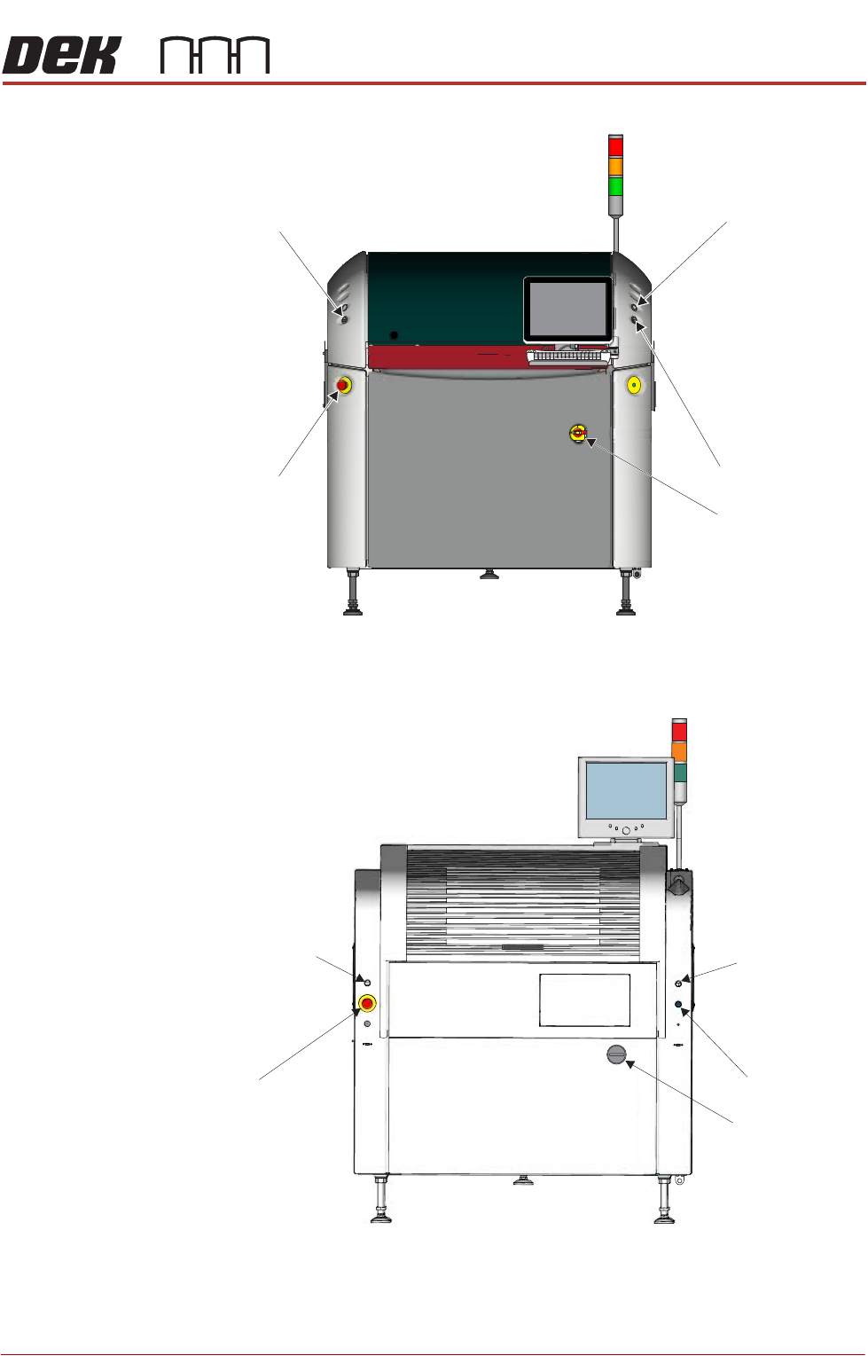
Figure 1-2 Type 2
Figure 1-3 Type 3
View on Front of Machine
Right Jog Button
System Button
Mains Isolator
Left Jog Button
E Stop
Left Jog Button
Right Jog Button
System Button
View on Front of Machine
E Stop
Mains Isolator
SAFETY FEATURES
GENERAL
1.12 Installation Manual Chapter Issue 15, Nov 19
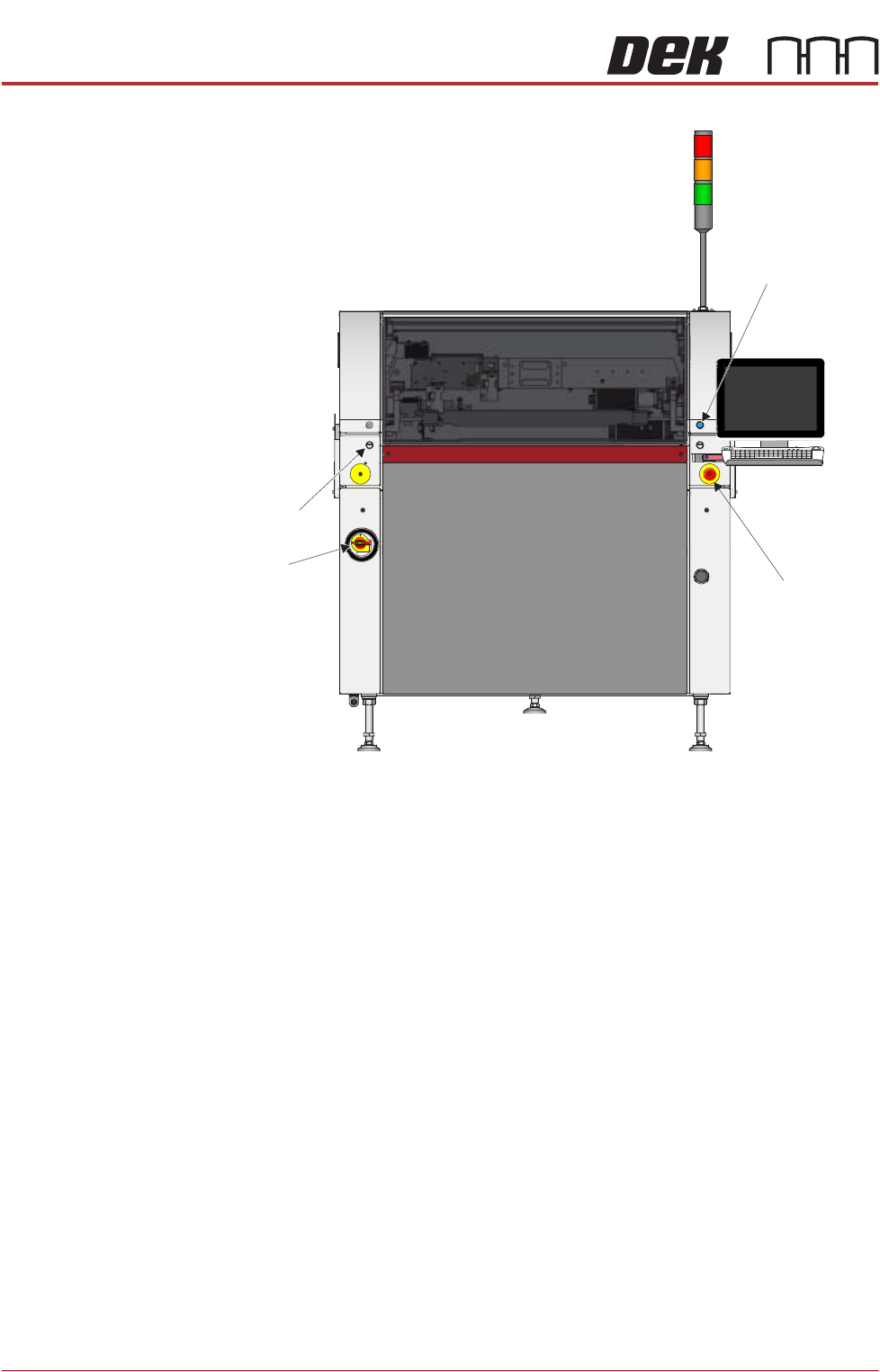
Figure 1-4 Type 4
View on Front of Machine
Left Jog Button
E Stop
System Button
Mains
Isolator
SAFETY FEATURES
GENERAL
Chapter Issue 15, Nov 19 Installation Manual 1.13
Figure 1-5 Type 5
Emergency Stop
(E Stop)
The printer is fitted with an E Stop which suspends all printer operations. The
switch is within easy reach of the operator and once pressed, the latching switch
requires resetting.
To reset the E Stop, turn the button clockwise until it unlatches.
Pressing the E Stop or opening the printhead cover cuts the servo axes power
supply. A warning of this condition is reported on the printer monitor.
E Stop Module
Shut Down
If the E Stop loop is opened by pressing the E Stop or opening the printhead
cover, an emergency stop is initiated via the E Stop module. When actuated the
following areas of the printer are rendered inactive: