88192278-01-19 Installation Master.pdf - 第192页
HIGH THROUGHPUT CONVEYOR (HTC) OPERATION 6.2 Installation Manual Chapter Issue 6, May 20 OPERA TIO N The 1/3 Stage Operation and F ast T ransfers Disabled buttons are LED illumi- nated push buttons and are configur ed as…
HIGH THROUGHPUT CONVEYOR (HTC)
INTRODUCTION
Chapter Issue 6, May 20 Installation Manual 6.1
CHAPTER 6 HIGH THROUGHPUT CONVEYOR (HTC)
INTRODUCTION
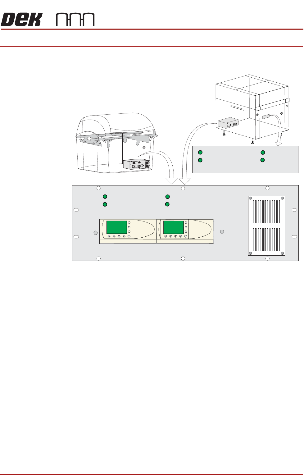
Figure 6-1 HTC Controller Location
The HTC controller (M27) enclosure is located behind the front maintenance
cover just below the mains isolator switch.
On Gemini and NeoHorizon printers the HTC controller (M27) enclosure is
located at the rear. For ease of access a remote switch panel is located behind
the front maintenance cover.
The M27 consists of a Programmable Logic Controller (PLC) for each auxiliary
conveyor. Above each PLC are the switches for selecting between 3-stage/
single stage and fast/normal mode.
On machine initialisation, each auxiliary conveyor PLC needs to detect the
machine ‘System Power’ and a ‘Downline Available’ signal before the system
starts operating. If the machine is being run in a stand-alone environment, the
‘Downline Available’ signal from the downline machine can be mimicked by
shorting pins 1 & 2 of loom Pt No 88160645-01 to the downline machine.
1/3 STAGE
OPERATION
1/3 STAGE
OPERATION
FAST TRANSFERS
DISABLED
FAST TRANSFERS
DISABLED
1/3 STAGE
OPERATION
1/3 STAGE
OPERATION
FAST TRANSFERS
DISABLED
FAST TRANSFERS
DISABLED
R/H CONVEYOR L/H CONVEYOR
ESC
OK
+
-
ESC
OK
+
-
Remote Switch Panel
R/H CONVEYOR L/H CONVEYOR
HIGH THROUGHPUT CONVEYOR (HTC)
OPERATION
6.2 Installation Manual Chapter Issue 6, May 20
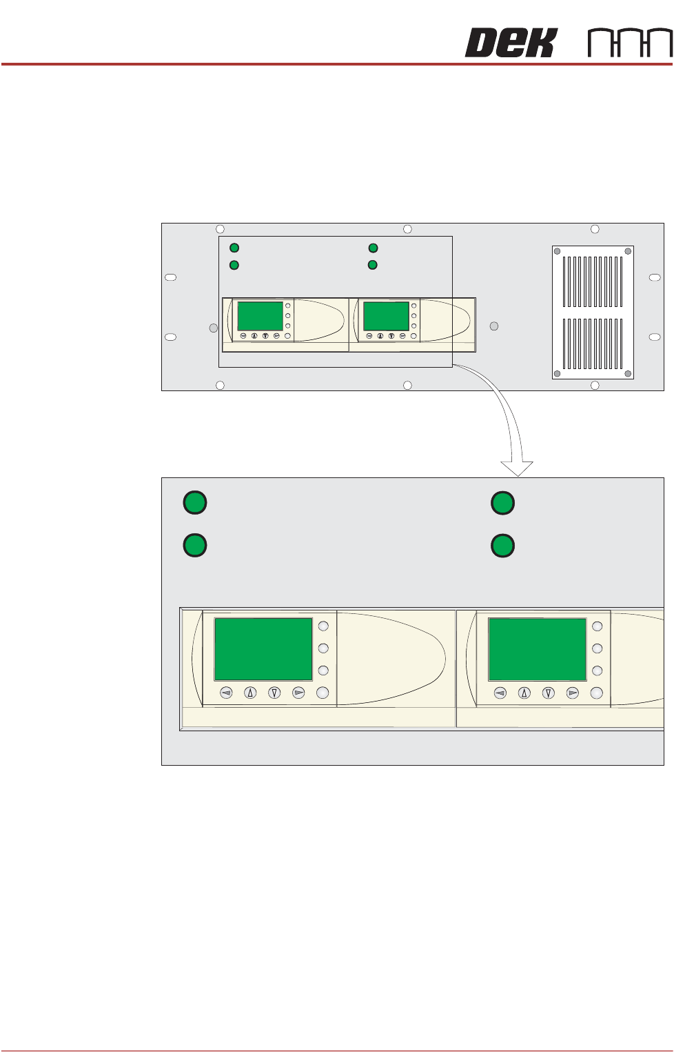
OPERATION The 1/3 Stage Operation and Fast Transfers Disabled buttons are LED illumi-
nated push buttons and are configured as follows:
3-Stage/Single
Stage Mode
For 3-stage mode, both 1/3 Stage Operation buttons must be OFF (LED
extinguished). The LCD screen on the PLC displays ‘3 Stage’ on the top line.
For single stage mode, both 1/3 Stage Operation buttons must be ON (LED
lit).The LCD screen on the PLC displays ‘1 Stage’ on the top line.
Fast/Normal Mode For a conveyor to operate in fast transfer mode, both Fast Transfer Disabled
buttons must be OFF (LED extinguished). The LCD screen on the PLC displays
‘Fst.Trans.’ on the bottom line for 5 seconds on power-up or when the button
is switched to OFF.
For a conveyor to operate in normal transfer mode, both Fast Transfer Disabled
buttons must be ON (LED lit). Normal transfer mode is not displayed on the
PLC.
1/3 STAGE
OPERATION
1/3 STAGE
OPERATION
FAST TRANSFERS
DISABLED
FAST TRANSFERS
DISABLED
R/H CONVEYOR L/H CONVEYOR
1/3 STAGE
OPERATION
1/3 STAGE
OPERATION
FAST TRANSFERS
DISABLED
FAST TRANSFERS
DISABLED
R/H CONVEYOR L/H CONVEYOR
ESC
OK
+
-
ESC
OK
+
-
ESC
OK
+
-
ESC
OK
+
-
HIGH THROUGHPUT CONVEYOR (HTC)
OPERATION
Chapter Issue 6, May 20 Installation Manual 6.3
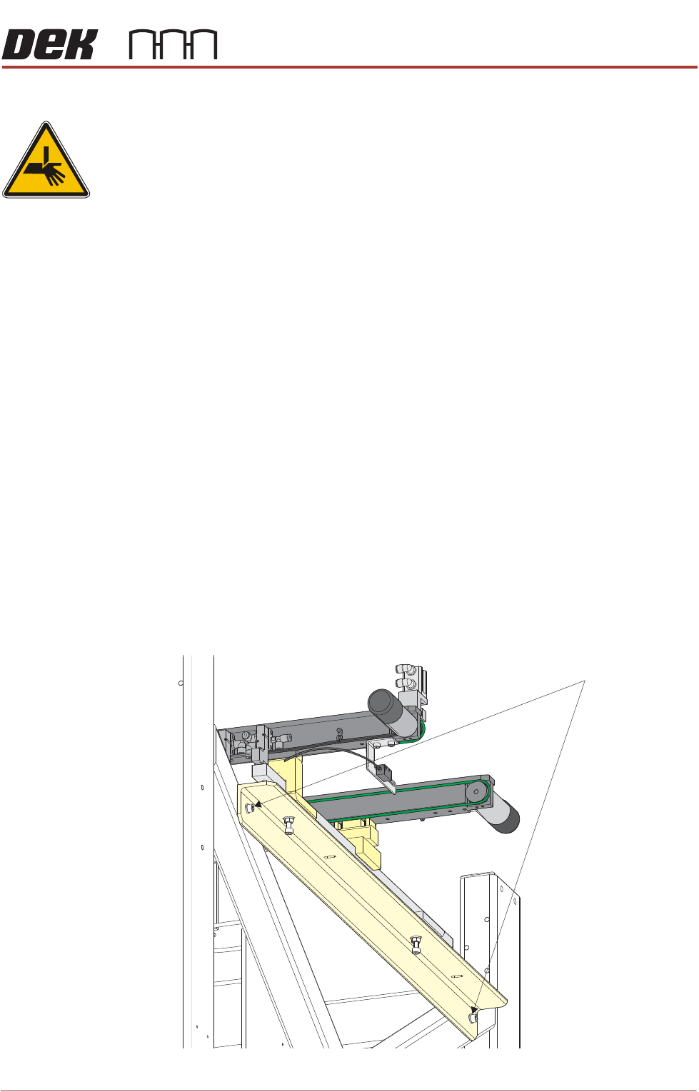
Auxiliary Conveyor Front Rail Parallelism
WARNING
BOARD CLAMPS. EXTREME CARE MUST BE EXERCISED WHEN WORKING IN
THE TOOLING AREA OF THE MACHINE TO AVOID INJURY. THE FOILS ON THE
FRONT AND REAR BOARD CLAMPS ARE VERY SHARP.
To check and if required adjust the auxiliary conveyors front rail parallelism,
carry out the following procedure at transport height:
NOTE
Before continuing with this procedure refer to the Pre-Power Up section of this
chapter. Check the integrity of the machine power connections before connect-
ing the printer and powering it up. Ensure that all transport brackets have been
removed prior to powering up. Use diagnostics to lift the transport rails to
transport height.
NOTE
The parallelism of the auxiliary conveyors rails is dependent on the front and
rear print station rails being parallel. Therefore, before any adjustment is carried
out an assessment of the parallelism of the print station rails must be carried out.
1. Manually adjust the print station rail width to 250mm.
2. Place one of the Board Clamp Setting Plates Part No. 88140403-01 onto the
print station transport belts.
3. Manually slide the setting plate back and forth from the print station to the
right hand auxiliary conveyor, ensuring the plate moves freely without
binding or jamming.
4. If adjustment is required on the right hand auxiliary conveyor, loosen the two
auxiliary conveyor securing bolts.
Auxiliary Conveyor Securing Bolts