88192278-01-19 Installation Master.pdf - 第194页
HIGH THROUGHPUT CONVEYOR (HTC) OPERATION 6.4 Installation Manual Chapter Issue 6, May 20 5. Carefully adjust the conveyor to obtai n front rail parallelism with the print station front rail. 6. Re-tighten the securing bo…
HIGH THROUGHPUT CONVEYOR (HTC)
OPERATION
Chapter Issue 6, May 20 Installation Manual 6.3
Auxiliary Conveyor Front Rail Parallelism
WARNING
BOARD CLAMPS. EXTREME CARE MUST BE EXERCISED WHEN WORKING IN
THE TOOLING AREA OF THE MACHINE TO AVOID INJURY. THE FOILS ON THE
FRONT AND REAR BOARD CLAMPS ARE VERY SHARP.
To check and if required adjust the auxiliary conveyors front rail parallelism,
carry out the following procedure at transport height:
NOTE
Before continuing with this procedure refer to the Pre-Power Up section of this
chapter. Check the integrity of the machine power connections before connect-
ing the printer and powering it up. Ensure that all transport brackets have been
removed prior to powering up. Use diagnostics to lift the transport rails to
transport height.
NOTE
The parallelism of the auxiliary conveyors rails is dependent on the front and
rear print station rails being parallel. Therefore, before any adjustment is carried
out an assessment of the parallelism of the print station rails must be carried out.
1. Manually adjust the print station rail width to 250mm.
2. Place one of the Board Clamp Setting Plates Part No. 88140403-01 onto the
print station transport belts.
3. Manually slide the setting plate back and forth from the print station to the
right hand auxiliary conveyor, ensuring the plate moves freely without
binding or jamming.
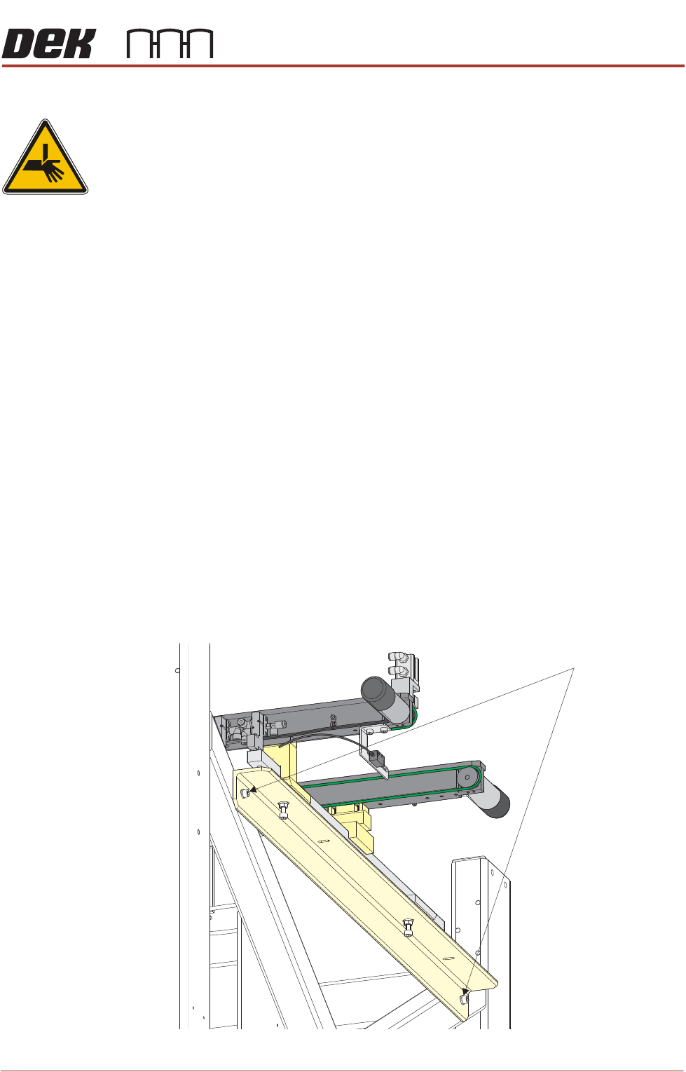
4. If adjustment is required on the right hand auxiliary conveyor, loosen the two
auxiliary conveyor securing bolts.
Auxiliary Conveyor Securing Bolts
HIGH THROUGHPUT CONVEYOR (HTC)
OPERATION
6.4 Installation Manual Chapter Issue 6, May 20
5. Carefully adjust the conveyor to obtain front rail parallelism with the print
station front rail.
6. Re-tighten the securing bolts and re-check for parallelism.
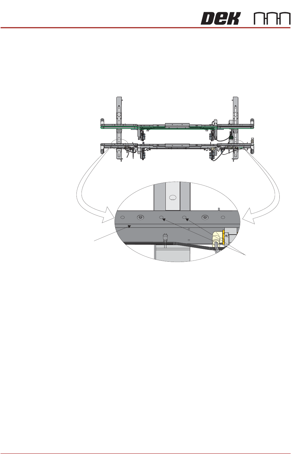
7. Further adjustment of the auxiliary conveyor can be achieved by loosening
the two front rail securing bolts, adjusting the rail to achieve parallelism and
re-tightening the rail securing bolts.
8. Repeat Steps 3 to 7 for the left hand auxiliary conveyor.
Front View of HTC Rails
Auxiliary Conveyor
Front Rail
Front Rail
Securing Bolts

HIGH THROUGHPUT CONVEYOR (HTC)
OPERATION
Chapter Issue 6, May 20 Installation Manual 6.5
Auxiliary Conveyor Rear Rail Parallelism
WARNING
BOARD CLAMPS. EXTREME CARE MUST BE EXERCISED WHEN WORKING IN
THE TOOLING AREA OF THE MACHINE TO AVOID INJURY. THE FOILS ON THE
FRONT AND REAR BOARD CLAMPS ARE VERY SHARP.
To check and if required adjust the auxiliary conveyors rear rail parallelism, carry
out the following procedure at transport height:
NOTE
1. Before continuing with this procedure refer to the Pre-Power Up section of
this chapter. Check the integrity of the machine power connections before
connecting the printer and powering it up. Ensure that all transport brackets
have been removed prior to powering up. Use diagnostics to lift the transport
rails to transport height.
2. The parallelism of the auxiliary conveyors rails is dependent on the front and
rear print station rails being parallel. Therefore, before any adjustment is
carried out an assessment of the parallelism of the print station rails must
be carried out.
3. Ensure that the auxiliary conveyor front rail is in alignment with the print
station front rail before any adjustment of the auxiliary conveyor rear rail
parallelism (refer to Auxiliary Conveyor Front Rail Parallelism section of this
chapter).