88192278-01-19 Installation Master.pdf - 第22页
SAFETY FEATURES GENERAL 1.10 Installation Manual Chapter Issue 15, Nov 19 GENERAL DEK printers incorporate safety features that provide a safe operating environ- ment for the operator and the printe r . All safety circui…
SAFETY FEATURES
PRINTER SAFETY FEATURES
Chapter Issue 15, Nov 19 Installation Manual 1.9
ELECTRO MECHANICAL HAZ-
ARDS REMOVING THIS COVER
EXPOSES ELECTROMECHANICAL
PARTS THAT HAVE THE POTENTIAL
TO CAUSE SERIOUS INJURY. DIS-
CONNECT AND LOCK OUT THE SYS-
TEM POWER BEFORE REMOVING
THIS COVER. REFER TO THE LOCK-
OUT PROCEDURE AT THE END OF
THIS CHAPTER.
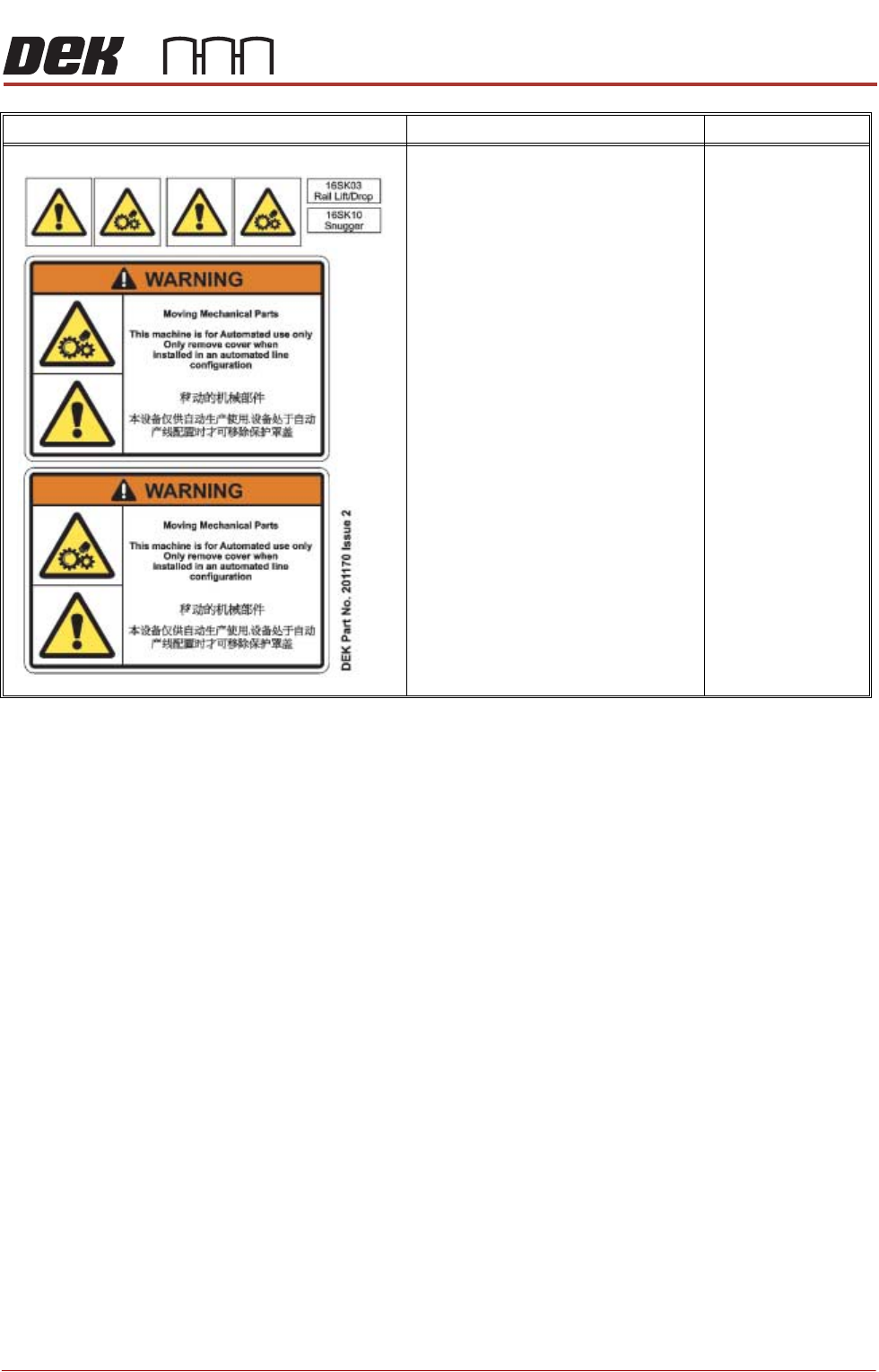
GENERAL WARNING
REFER TO THE OPERATOR MANUAL
OR THE FRONT OF THIS CHAPTER
FOR A LIST OF ALL WARNINGS AND
THEIR DEFINITIONS.
SAFETY COVERS
WARNING DEFINITION LOCATION
SAFETY FEATURES
GENERAL
1.10 Installation Manual Chapter Issue 15, Nov 19
GENERAL
DEK printers incorporate safety features that provide a safe operating environ-
ment for the operator and the printer.
All safety circuits have been designed to meet the safety requirements as
outlined in the printers’ CE Declaration of Conformity. The circuits check for
welded contacts before resetting. Additional safety is achieved by duplication of
the power contactors to provide redundancy.
There are five printer cover designs:
• Type 1
• Type 2
• Type 3
• Type 4
• Type 5
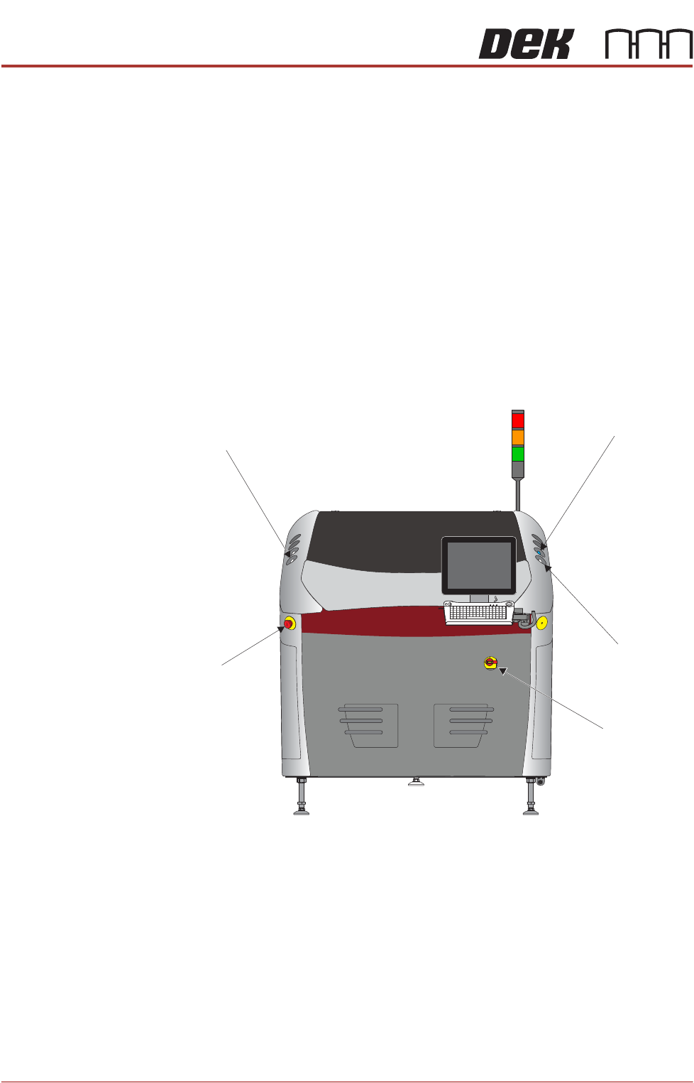
Figure 1-1 Type 1
Left Jog Button
System Button
Right Jog Button
View on Front of Machine
Mains Isolator
E Stop
SAFETY FEATURES
GENERAL
Chapter Issue 15, Nov 19 Installation Manual 1.11
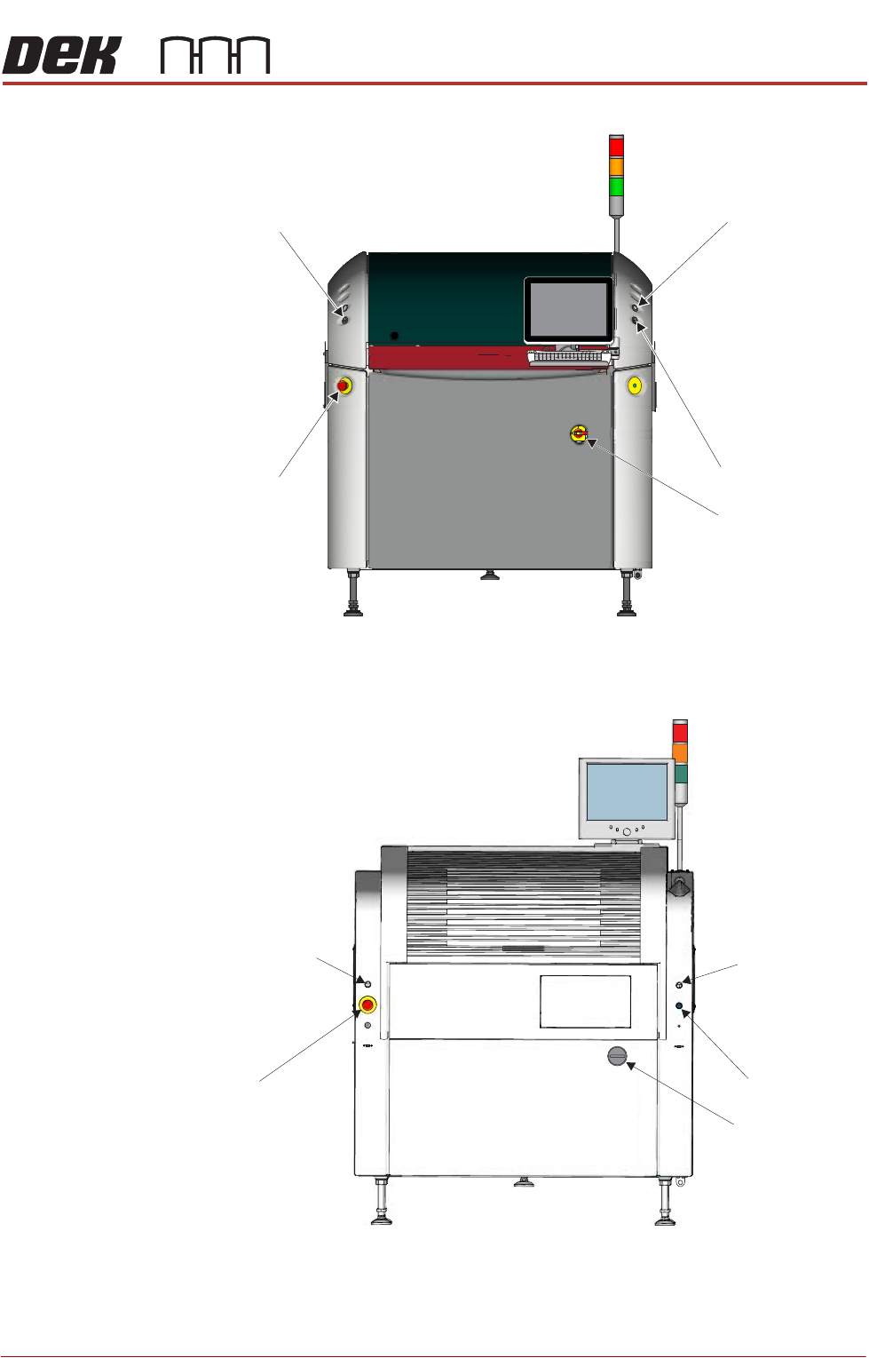
Figure 1-2 Type 2
Figure 1-3 Type 3
View on Front of Machine
Right Jog Button
System Button
Mains Isolator
Left Jog Button
E Stop
Left Jog Button
Right Jog Button
System Button
View on Front of Machine
E Stop
Mains Isolator