88192278-01-19 Installation Master.pdf - 第113页
PRINTER PREPARATION TRANSIT BRACKETS AND SCREWS REMOVAL Chapter Issue 15, May 20 Installation Manual 4.11 Paste Dispenser T ransit Screw 1. Remove the paste dispenser transit screw that secures the belt clamp bracket to …
PRINTER PREPARATION
TRANSIT BRACKETS AND SCREWS REMOVAL
4.10 Installation Manual Chapter Issue 15, May 20
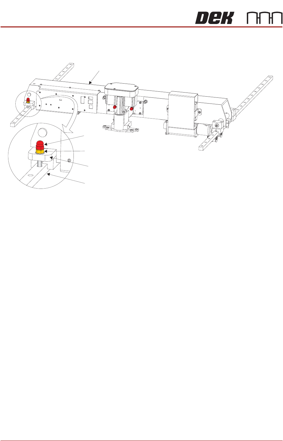
Print Carriage
Transit Screw
1. Loosen the M8 locking nut that secures the transit screw to the print carriage
compliant bearing block.
2. Remove the print carriage transit screw that secures the print carriage
compliant bearing block to the left linear guide rail. Ensure that the crinkle
washer below the locking nut is also removed.
3. Locate the re-sealable polythene bag taped to the print carriage.
4. Remove the plastic cap from the bag and fit into the hole that the transit
screw occupied on the left linear guide rail.
Print Carriage
Transit Screw
Print Carriage Compliant Bearing Block
Left Linear Guide Rail
Locking Nut and Crinkle Washer
PRINTER PREPARATION
TRANSIT BRACKETS AND SCREWS REMOVAL
Chapter Issue 15, May 20 Installation Manual 4.11
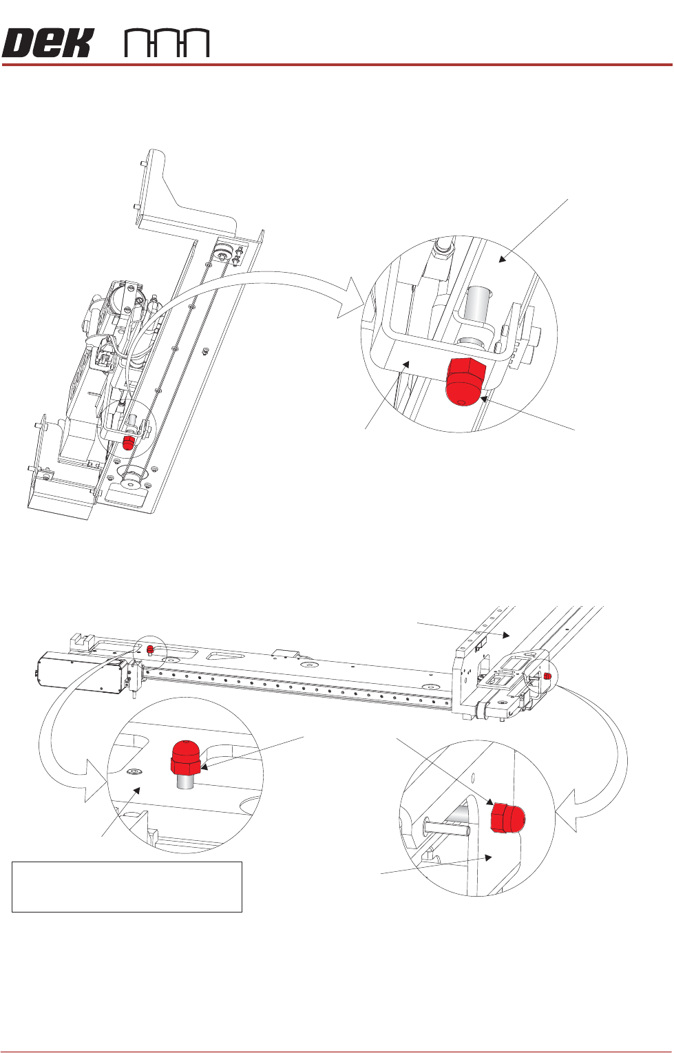
Paste Dispenser
Transit Screw
1. Remove the paste dispenser transit screw that secures the belt clamp
bracket to the paste dispenser mounting tray.
Camera Transit
Screws (Rotary
Drive)
1. Remove the transit screw that secures the camera beam to the camera X
drag chain bracket.
2. Remove the transit screw that secures the camera Y drag chain bracket to
the right hand printhead.
View on Right Hand Underside of Paste Dispenser
Transit Screw
Paste Dispenser Mounting Tray
Belt Clamp Bracket
Note
Camera X Drag Chain Bracket is hidden
from view by the Camera Beam
Transit Screws
Camera Beam
Right Hand Printhead
Camera Y Drag
Chain Bracket
PRINTER PREPARATION
TRANSIT BRACKETS AND SCREWS REMOVAL
4.12 Installation Manual Chapter Issue 15, May 20
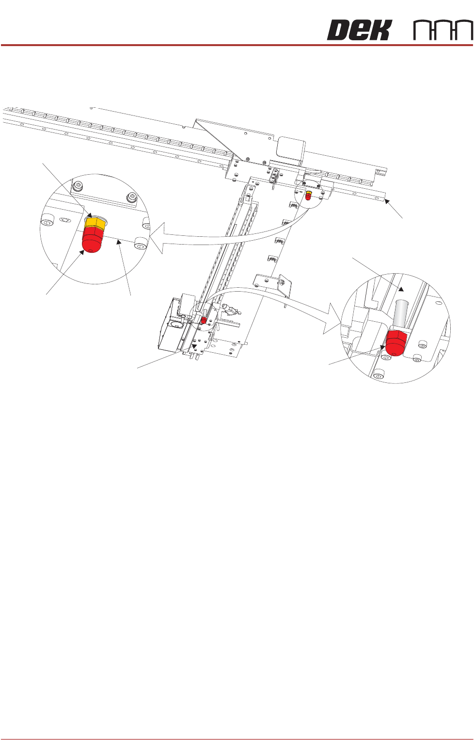
Camera Transit
Screws (Linear
Drive)
1. Loosen the lock nut that secures the transit screw to the camera Y plate.
2. Remove the transit screw that secures the camera Y plate to the camera Y
linear bearing ensuring that the lock nut and crinkle washer are removed
with the transit screw.
3. Remove the transit screw that secures the camera X drag chain bracket to
the camera beam extrusion.
Under Screen
Cleaner
1. Snip the cable ties securing the piece of card to the top of the under screen
cleaner.
2. Remove the cable ties and the piece of card from the printer.
This concludes the transit bracket and screw removal procedure. Transit
brackets, screws and associated fasteners should be stored for future reuse.
Printer Relocation In the event of printer relocation, refer to the Technical Reference Manual,
Transportation chapter for transit bracket and screw fitment procedure.
View on Right Hand Underside of Camera Beam
Transit Screw
Transit Screw
Camera Y Plate
Camera Y Linear Bearing
Camera X Drag Chain Bracket
Camera Beam Extrusion
Lock Nut and
Crinkle Washer