88192278-01-19 Installation Master.pdf - 第119页
PRINTER PREPARATION PRINTER HEIGHT AND LEVELLING Chapter Issue 15, May 20 Installation Manual 4.17 T ype 4 Printers Before operation, Printers A and B must be installed at the correct height, levelled and aligned using t…

PRINTER PREPARATION
PRINTER HEIGHT AND LEVELLING
4.16 Installation Manual Chapter Issue 15, May 20
14. Recheck the printer is level.
15. Recheck the printer height has not been disturbed.
16. Remove the engineering level from the printer.
PRINTER PREPARATION
PRINTER HEIGHT AND LEVELLING
Chapter Issue 15, May 20 Installation Manual 4.17
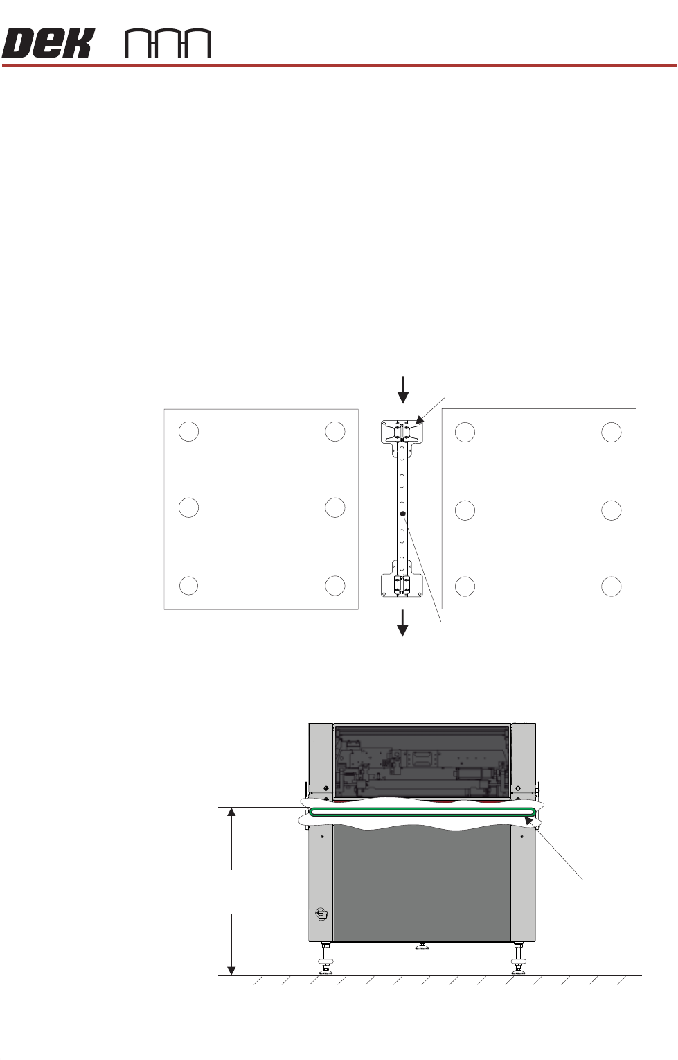
Type 4 Printers Before operation, Printers A and B must be installed at the correct height,
levelled and aligned using the supplied Location Plate Assembly.
NOTE
1. The orientation of the machine location plate is normally in the upline to
downline direction with the ‘V’ plates nearest the upline end. However,
where there is an item, such as the pneumatic inlet connector, in the vicinity
of the ‘V’ plates, the plates need to be located at the opposite end to avoid
creating an obstruction. Turn the location plate around. In the following
procedure, references to feet numbers at the rear of the printer now apply
to feet located at the front.
2. The ‘V’ plates can be removed and moved to opposite corners if the printers
have air inlet connectors located on opposite corners.
For this procedure, refer to the following diagram indicating feet numbers.
The height of each printer is governed by the external machines in the line, and
ranges from 840mm to 980mm. The height is measured from the floor to the top
of the transport belts.
Height to Top
of Transport Belts
8 mm to 980mm95
View on Front of Machine
Transport Belts
PRINTER PREPARATION
PRINTER HEIGHT AND LEVELLING
4.18 Installation Manual Chapter Issue 15, May 20
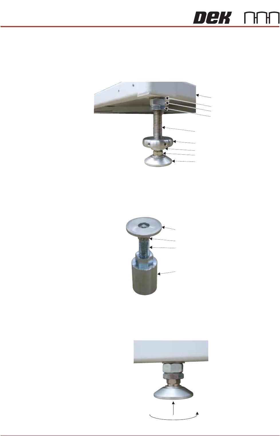
The transport height may be adjusted as low as 830mm by removing the M24
full nut on each of the legs. In the event of the transport height being adjusted
above 839mm at a later date, the M24 full nut must be refitted. The locating
collar positions the printer accurately against the V-blocks on the Locator Plate
Assembly.
NOTE
To achieve reliable DEK SPC testing and Cp/Cpk results, the printer legs must
be secured correctly to the frame to increase the rigidity of the printer.
NOTE
The centre mounting foot (6) is separate and is only used for initial levelling.
Levelling and
Positioning (Printer
A)
1. Raise the rear centre mounting foot (5) to the highest position to avoid
contact with the floor plate.
Washer
Machine Frame
M24 Full Nut
Half Nut
Locating Collar
Leg Bolt
Foot
Half Nut
Leg Adjusting Nut
Swivel Plate
Foot
Leg Bolt
Full Nut