88192278-01-19 Installation Master.pdf - 第130页
PRINTER PREPARATION PRINTER ASSEMBLY 4.28 Installation Manual Chapter Issue 15, May 20 T ype 2 Covers 1. Fit the tricolour beacon to the beacon bracket ensuring that the cable is not trapped between the beacon and t he c…
PRINTER PREPARATION
PRINTER ASSEMBLY
Chapter Issue 15, May 20 Installation Manual 4.27
PRINTER ASSEMBLY
Assemble the following printer components and assemblies:
Tricolour Beacon
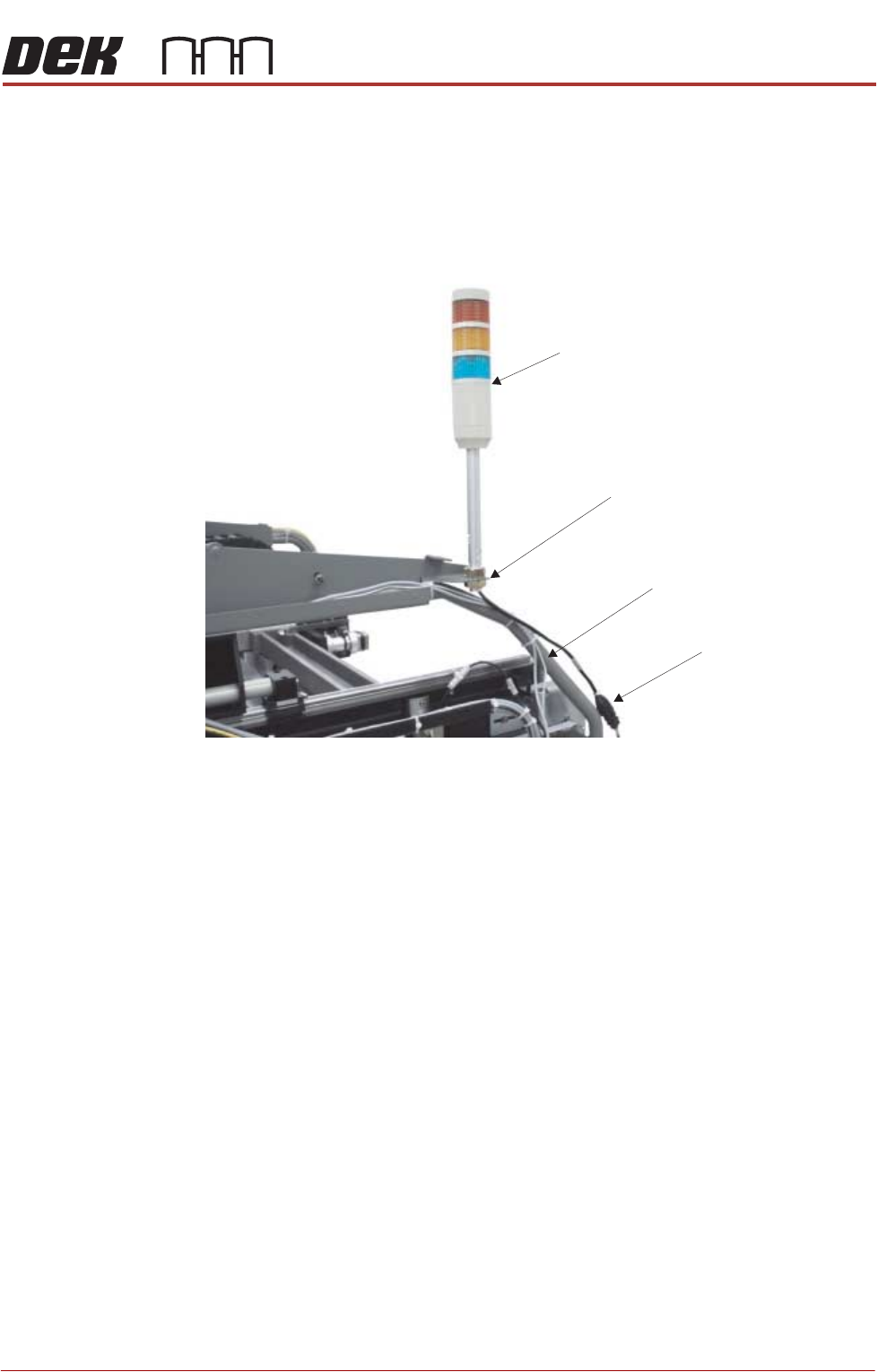
Type 1 Covers 1. Fit the tricolour beacon to the beacon bracket ensuring that the cable is not
trapped between the beacon and the cover frame.
2. Connect the tricolour beacon connection 14PL07 to 14SK07.
3. Cable tie the loose cable to the cover frame.
View on Right Hand Side of Machine (covers removed)
Beacon Connection
Tricolour Beacon
Beacon Bracket
Cover Frame
PRINTER PREPARATION
PRINTER ASSEMBLY
4.28 Installation Manual Chapter Issue 15, May 20
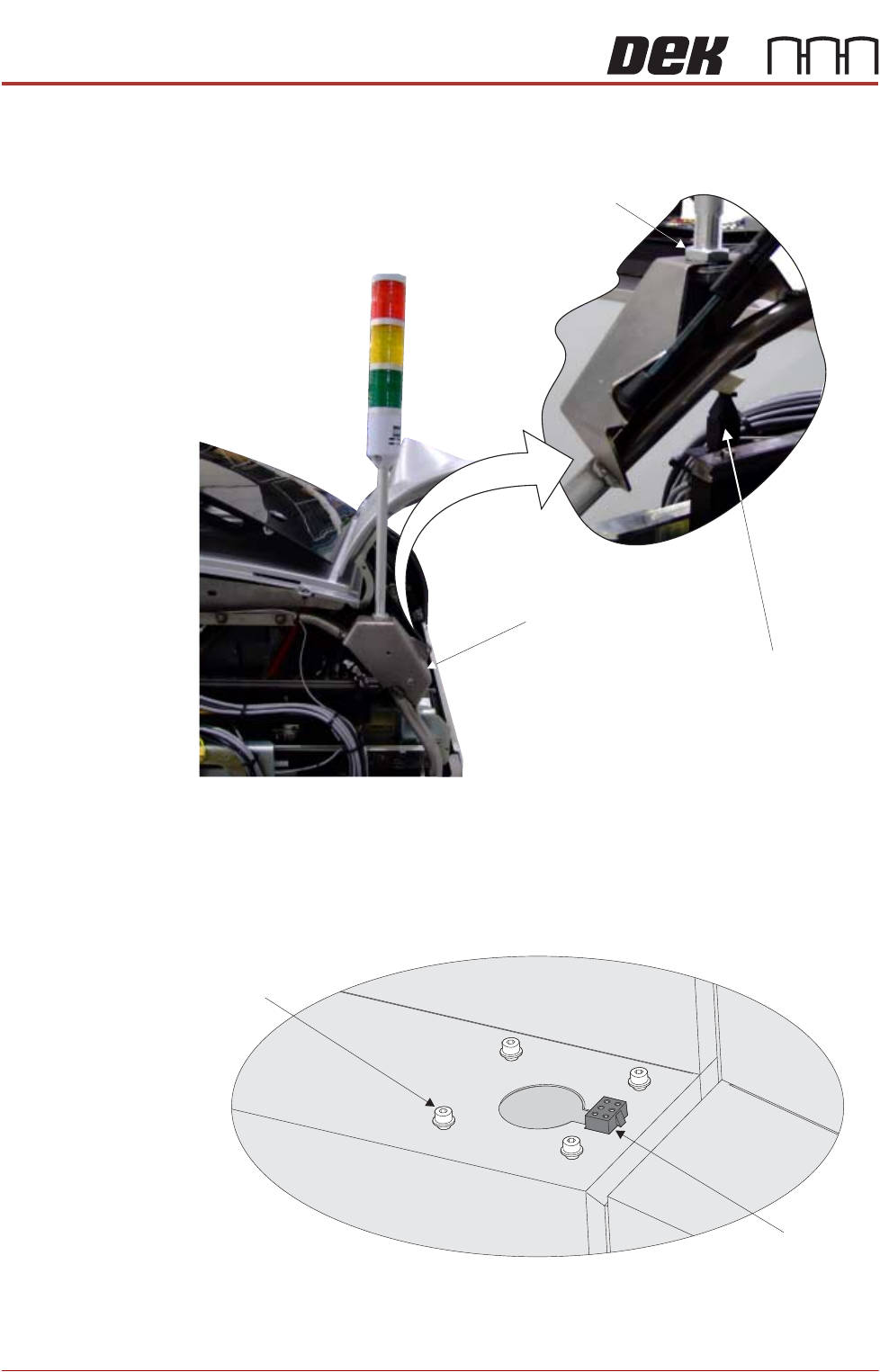
Type 2 Covers 1. Fit the tricolour beacon to the beacon bracket ensuring that the cable is not
trapped between the beacon and the cover frame.
2. Connect the tricolour beacon connection 14PL07 to 14SK07.
3. Cable tie the loose cable to the cover frame.
Type 3 Covers 1. Using a 3mm Allen key, remove the beacon bracket securing screws from
the printer cover.
2. Maintaining hold of the socket 14SK07 (to prevent the socket from falling
View on Rear of Printer
Beacon Connection
Beacon Bracket
Beacon Locking Nut
Beacon Bracket
Securing Screws
(in 4 positions)
Beacon Connector
(14SK07)
View on Right Hand Side of the Machine
PRINTER PREPARATION
PRINTER ASSEMBLY
Chapter Issue 15, May 20 Installation Manual 4.29
into the printer through the hole), lift the socket from its location.
3. Connect the tricolour beacon connection 14PL07 to 14SK07 and feed down
through the hole in the cover with any surplus cable.
4. Fit the beacon bracket to the printer cover using the four beacon bracket
securing screws ensuring that any cables are not trapped between the
beacon bracket and the cover.
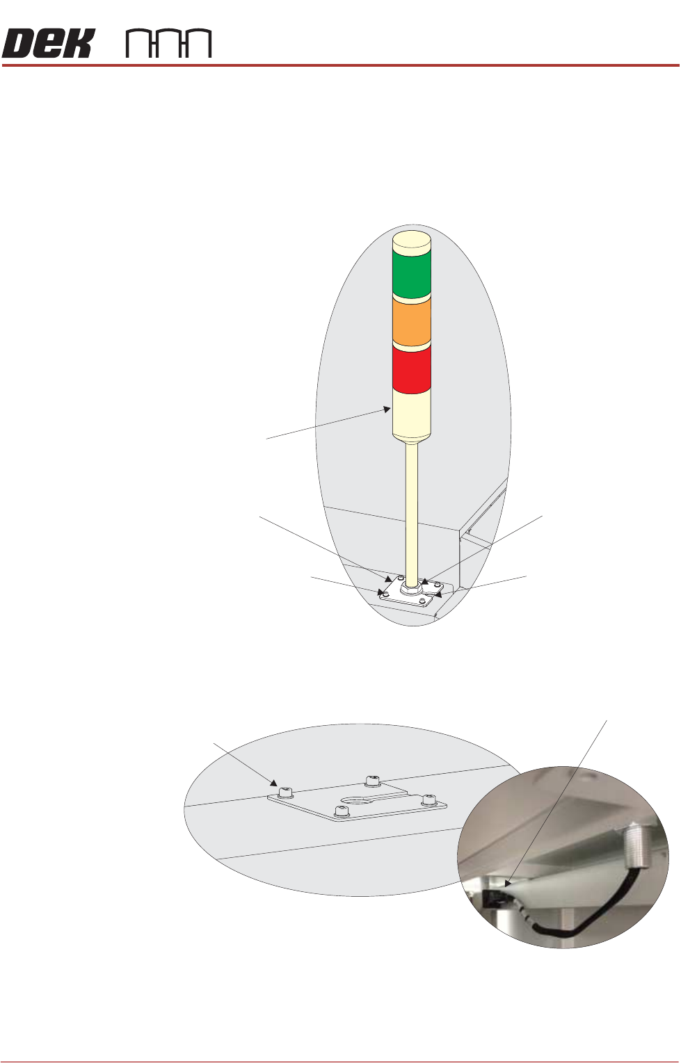
Type 4 Covers 1. Using a 3mm Allen key, remove the beacon bracket securing screws from
the printer cover.
2. Remove the Rear Corner Panel to reveal socket 14SK07.
3. Feed the tricolour beacon connection 14PL07 down through the hole in the
cover with any surplus cable.
Beacon Bracket
Tricolour Beacon
Beacon Securing Nut
Beacon Bracket Cut-Out
Beacon Bracket Securing
Screws (in 4 positions)
Beacon Bracket
Securing Screws
(in 4 positions)
View on Underside of Beacon Bracket
Beacon Connector
()14SK07
View on Right Hand Side of the Machine