88192278-01-19 Installation Master.pdf - 第136页
PRINTER PREPARATION PRINTER ASSEMBLY 4.34 Installation Manual Chapter Issue 15, May 20 located in the key sl ots. 1 1. Secure the monitor using the monitor securing screw . Monitor Fixing Bracket Monitor Securing Screw
PRINTER PREPARATION
PRINTER ASSEMBLY
Chapter Issue 15, May 20 Installation Manual 4.33
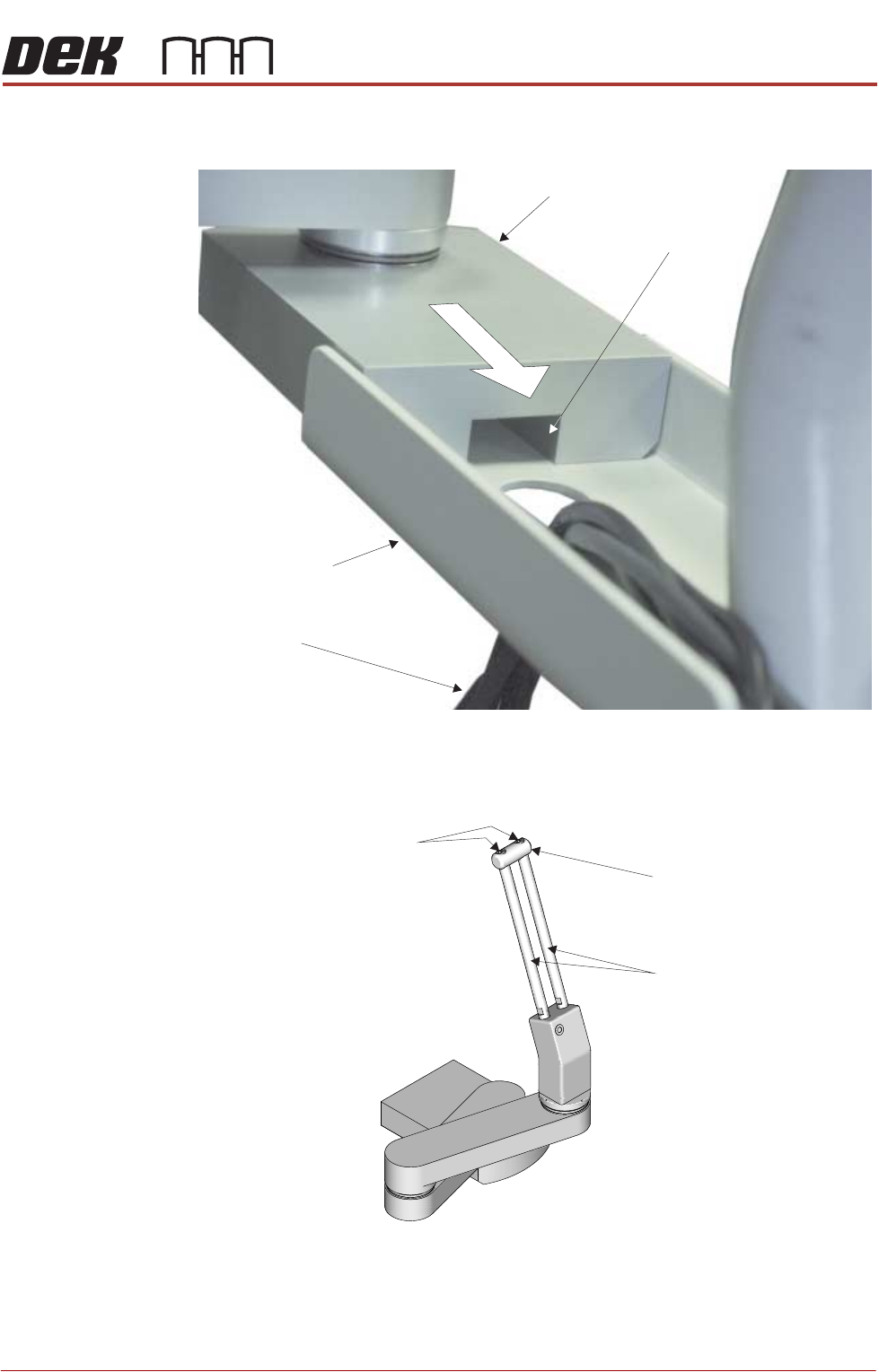
5. Fit the monitor arm to the monitor bracket ensuring that no cables are
trapped between the arm and bracket.
6. Secure the monitor arm to the bracket with three screws from below.
7. Using a 2.5mm Allen key, remove the end block from the top of the
adjustment bars.
8. Slide the monitor bracket on to the adjustment bars and tighten the locking
thumbscrew.
9. Refit the end block.
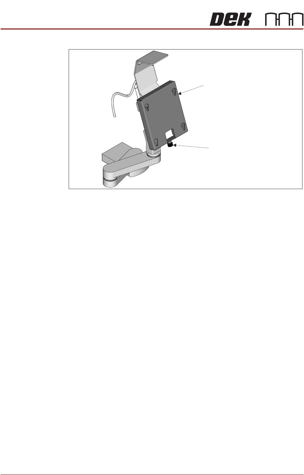
10. Fit the monitor to the monitor fixing bracket ensuring that all four studs are
Monitor Support Arm
MMI Cable Channel
MMI Cables
Monitor Support
Arm Bracket
Securing Screws
End Block
Adjustment Bars
PRINTER PREPARATION
PRINTER ASSEMBLY
4.34 Installation Manual Chapter Issue 15, May 20
located in the key slots.
11. Secure the monitor using the monitor securing screw.
Monitor Fixing Bracket
Monitor Securing Screw
PRINTER PREPARATION
PRINTER ASSEMBLY
Chapter Issue 15, May 20 Installation Manual 4.35
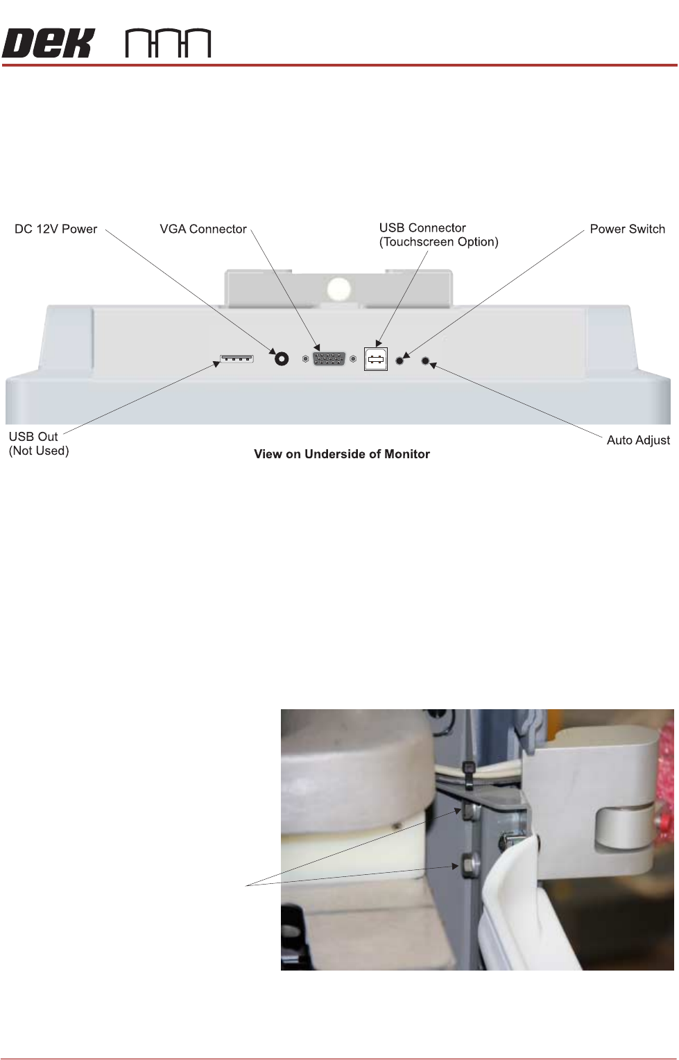
12. Connect the following cables to the monitor:
• Monitor Power Cable (DC)
•VGA Cable
• Touchscreen Cable (USB)
13. Connect the Rear Monitor USB Connector cable to the remaining USB cable
coming from the printer.
14. Locate the free floating USB connector inside the right hand side of the
printer, behind the front panel.
15. Connect the keyboard.
16. Refit the front panel.
Type 2 Covers Use the following procedure to fit the monitor:
1. Remove the front panel.
2. Using a 13mm spanner, fit the monitor arm to the printer frame.
Securing Bolts