88192278-01-19 Installation Master.pdf - 第190页
POWER UP SEQUENCE MACHINE POWER UP SEQUENCE 5.14 Installation Manual Chapter Issue 10, Nov 19

POWER UP SEQUENCE
MACHINE POWER UP SEQUENCE
Chapter Issue 10, Nov 19 Installation Manual 5.13
23. Select Back
24. Select Back
25. Select Barcodes.
26. Use the documentation supplied with the reader to setup the language,
keyboard format and barcode symbolism.
Configuring the
Handheld Barcode
Reader
To configure the handheld barcode reader:
1. Using the Manufacturer’s Quick Reference Guide, find the page with the
barcodes.
2. Using the barcode reader, scan the barcode entitled: USB COM Emulation.
The unit emits a beep, the LED turns green.
Testing the
Handheld Barcode
Reader
To test the handheld barcode reader:
1. Open Notepad software from the machines Windows Start Menu.
2. Using the barcode reader, scan an example barcode from the Manufac-
turer’s Quick Reference Guide.
3. If Notepad displays barcode content as expected, then the handheld bar-
code reader is working correctly.
If the barcode read is unsuccessful, see the Troubleshooting section below.
Troubleshooting If the barcode read is unsuccessful, try the following:
1. Check all physical connections of the hardware (barcode reader, cables/
looms etc).
2. Re-configure the barcode reader and re-test.
3. Check troubleshooting information in barcode reader’s Manufacturer’s
handbook(s).
4. Escalate the issue to ASM Customer Support.

POWER UP SEQUENCE
MACHINE POWER UP SEQUENCE
5.14 Installation Manual Chapter Issue 10, Nov 19
HIGH THROUGHPUT CONVEYOR (HTC)
INTRODUCTION
Chapter Issue 6, May 20 Installation Manual 6.1
CHAPTER 6 HIGH THROUGHPUT CONVEYOR (HTC)
INTRODUCTION
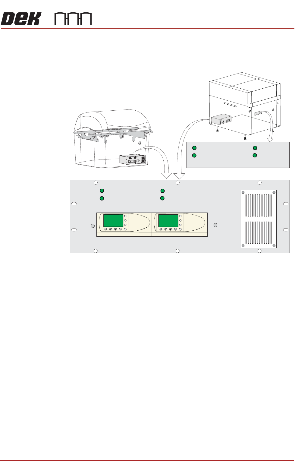
Figure 6-1 HTC Controller Location
The HTC controller (M27) enclosure is located behind the front maintenance
cover just below the mains isolator switch.
On Gemini and NeoHorizon printers the HTC controller (M27) enclosure is
located at the rear. For ease of access a remote switch panel is located behind
the front maintenance cover.
The M27 consists of a Programmable Logic Controller (PLC) for each auxiliary
conveyor. Above each PLC are the switches for selecting between 3-stage/
single stage and fast/normal mode.
On machine initialisation, each auxiliary conveyor PLC needs to detect the
machine ‘System Power’ and a ‘Downline Available’ signal before the system
starts operating. If the machine is being run in a stand-alone environment, the
‘Downline Available’ signal from the downline machine can be mimicked by
shorting pins 1 & 2 of loom Pt No 88160645-01 to the downline machine.
1/3 STAGE
OPERATION
1/3 STAGE
OPERATION
FAST TRANSFERS
DISABLED
FAST TRANSFERS
DISABLED
1/3 STAGE
OPERATION
1/3 STAGE
OPERATION
FAST TRANSFERS
DISABLED
FAST TRANSFERS
DISABLED
R/H CONVEYOR L/H CONVEYOR
ESC
OK
+
-
ESC
OK
+
-
Remote Switch Panel
R/H CONVEYOR L/H CONVEYOR