88192278-01-19 Installation Master.pdf - 第159页
PRINTER PREPARATION PRINTER ASSEMBLY Chapter Issue 15, May 20 Installation Manual 4.57 9. Connect the following to the ProFlow A Tx connectors on the right hand side of the print carriage. • Archimedes Screw Power (9PL10…
PRINTER PREPARATION
PRINTER ASSEMBLY
4.56 Installation Manual Chapter Issue 15, May 20
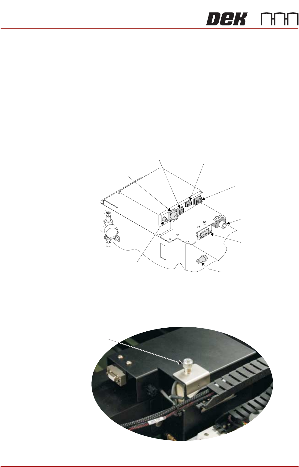
7. Connect the following to the ProFlow ATx connections on the left hand side
of the print carriage:
• Conditioning Grid Motor Power (9PL96)
• Head Empty Sensor (9PL77)
• Print Medium Cartridge Air Feed
• ProFlow Home (9PL08)
• Z-axis Stepper Motor Power (9PL17)
• Print Medium Low Sensor and ProFlow Fitted Link (9PL61)
• Conditioning Grid Motor CAN (9PL98)
• Piston Down Air Feed
8. Using a crosshead screwdriver, connect the drag chain carrying the right
hand side connectors to the right hand side of the print carriage.
Conditioning Grid
Motor CAN (9SK98)
Print Medium Low
Sensor and ProFlow
Fitted Link (9SK61)
Piston Down Air Feed
Z Axis Stepper
Motor Power (9SK17)
Print Medium
Cartridge
Air Feed
Conditioning Grid
Motor Power (9SK96)
ProFlow Home (9SK08)
Head Empty Sensor (9SK77)
View on Print Carriage Left Side
View on Print Carriage Top Face
Right Side Drag
Chain Screw
PRINTER PREPARATION
PRINTER ASSEMBLY
Chapter Issue 15, May 20 Installation Manual 4.57
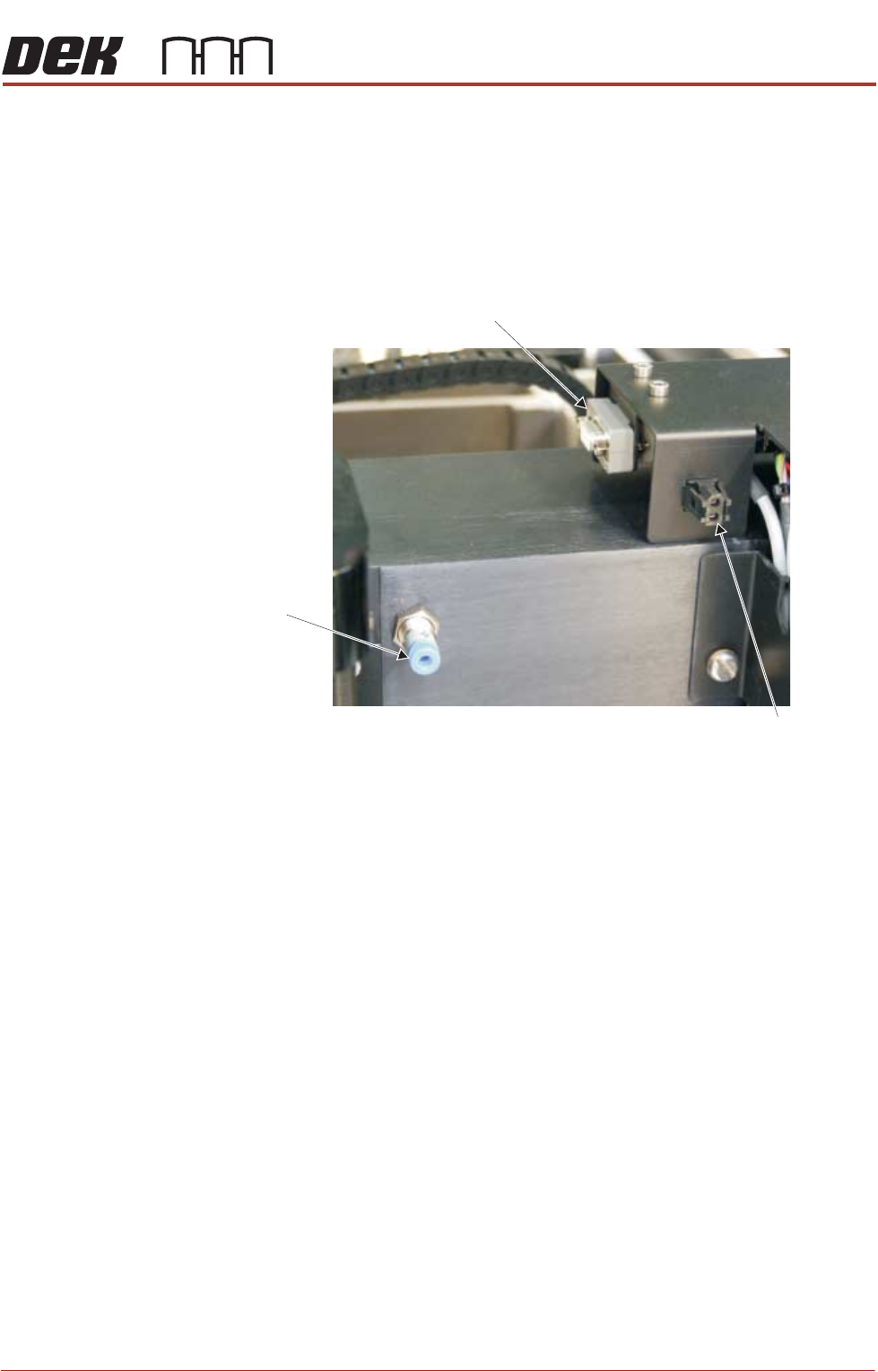
9. Connect the following to the ProFlow ATx connectors on the right hand side
of the print carriage.
• Archimedes Screw Power (9PL100)
• Paste Load Feedback (9PL108)
• Piston Up Air Feed
View on Print Carriage Right Side
Archimedes Screw
Power (9SK100)
Paste Load
Feedback (9SK108)
Piston Up
Air Feed
PRINTER PREPARATION
PRINTER ASSEMBLY
4.58 Installation Manual Chapter Issue 15, May 20
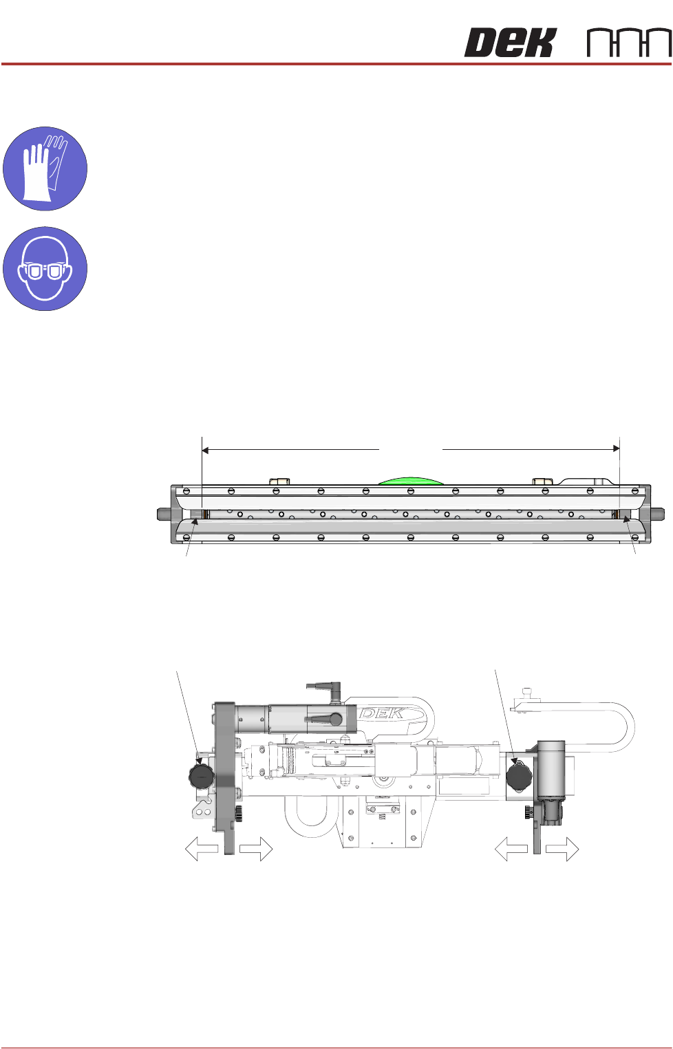
Fit Transfer Head
MANDATORY
TOXIC CHEMICALS MAY BE PRESENT. SAFETY GLOVES MUST BE WORN.
MANDATORY
TOXIC CHEMICALS MAY BE PRESENT. EYE PROTECTION MUST BE WORN.
To adjust the mount brackets and fit a transfer head to the ProFlow ATx mount,
carry out the following:
1. Determine the size of the transfer head to be fitted. If the size of the transfer
head is not known, measure the distance between the inside edges of the
skis.
2. On the ProFlow ATx mount, unscrew the left hand side thumbscrew until the
thread is released.
3. Pull on the left hand side thumbscrew until it is free from the mount hole.
4. Slide the left hand side mount bracket until it is aligned with the correct hole
for the size of the transfer head being used (for guidance on how to select
the correct mount hole for the transfer head being installed, see the diagram
Transfer Head Underside View
XXXmm
Ski
Ski
View On Front of Transfer Head
Left Thumbscrew
Right Thumbscrew
Left Mount Bracket Right Mount Bracket