88192278-01-19 Installation Master.pdf - 第107页
PRINTER PREPARATION TRANSIT BRACKETS AND SCREWS REMOVAL Chapter Issue 15, May 20 Installation Manual 4.5 TRANSIT BRACKETS AND SCREWS REMOV AL NOTE All transit brackets and screws must be removed from the printer before p…
PRINTER PREPARATION
GENERAL
4.4 Installation Manual Chapter Issue 15, May 20
WARNING
BOARD CLAMPS. EXTREME CARE MUST BE EXERCISED WHEN WORKING IN
THE TOOLING AREA OF THE MACHINE TO AVOID INJURY. THE FOILS ON THE
FRONT AND REAR BOARD CLAMPS ARE VERY SHARP.
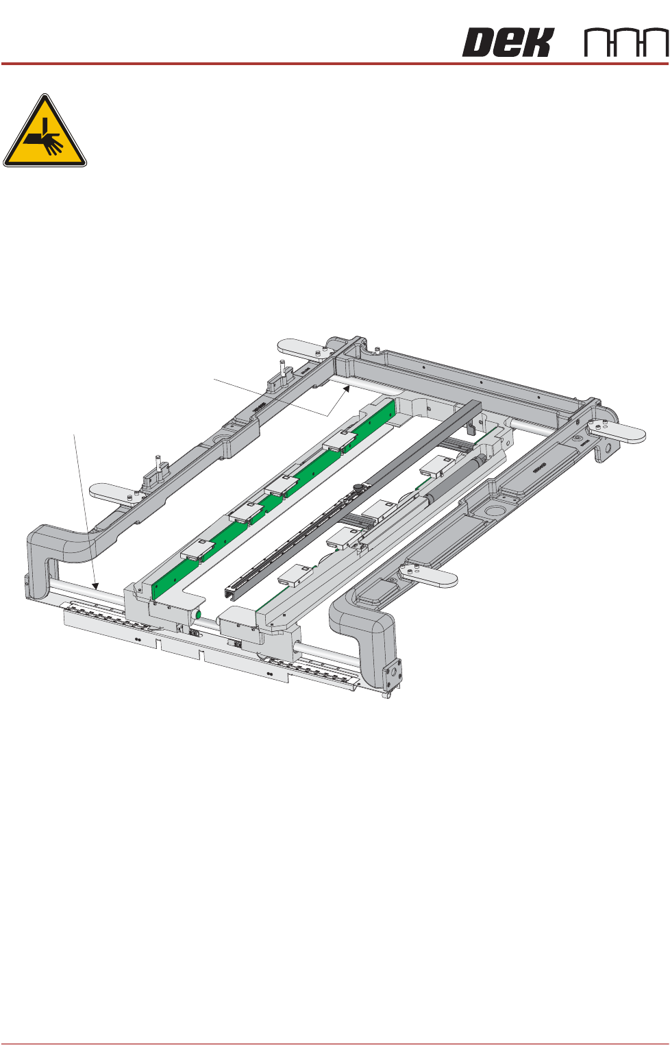
The front and rear board clamp foils, where fitted, are greased for protection
during transportation. This grease protection must to be removed completely
using a lint free cloth.
ASM Chase The front and rear guide bars are coated with multi-purpose oil for
transportation. Using a lint free cloth, thoroughly wipe the bars to remove the oil
completely.
Figure 4-2 Grease Protection - ASM
Front Guide Bar
Rear Guide Bar
PRINTER PREPARATION
TRANSIT BRACKETS AND SCREWS REMOVAL
Chapter Issue 15, May 20 Installation Manual 4.5
TRANSIT BRACKETS AND SCREWS REMOVAL
NOTE
All transit brackets and screws must be removed from the printer before power
is applied. Printer damage may occur if transit brackets or screws are not
removed prior to power up. Transit brackets and screws are red in colour for
easy identification.
To remove the transit brackets and screws from the printer, remove/open the
rear printhead cover. On Type 1 cover printers, remove the two upper side
panels as detailed in the Covers chapter.
Transit Brackets The transit brackets include the following:
• Front Transit Bracket
• Rear Transit Bracket
• Rear Chase Transit Bracket
• Cover Frame Transit Bracket (For printers with Anti Vibration (AV) mounts
fitted to the covers frame)
The following procedure must be adhered to and care must be taken to ensure
that the chase/ASM is released in a controlled manner to prevent damage to
the roller bearings or the actuators.
NOTE
In the following procedure, the numbers in brackets ( ) refer to Figures 4-3 The
Front and Rear Transit Brackets and 4-4 Rear Chase Transit Brackets.
To remove the chase transit brackets, carry out the following procedure:
1. Using a 13mm spanner, loosen the four M8 nuts (3) directly below the front
and rear transit brackets (2), Chase Transit Brackets figure refers.
2. Slowly loosen the four M8 nuts (3) above the front and rear transit brackets
(2) to lower the roller counter plates onto the rollers bearings.
3. Using a 4mm Allen key, remove the M5 cap head screws (9) and washers
(10) that attach the adaptor bracket (8) to the left and right printheads.
4. Remove the four M8 nuts (3) and washers (4) above the front and rear transit
brackets (2).
5. Remove the front and rear transit brackets (2) from the M8 chase studs (1).
6. Loosen the transit adjustment screw lock nut (6) on the front and rear transit
brackets (2).
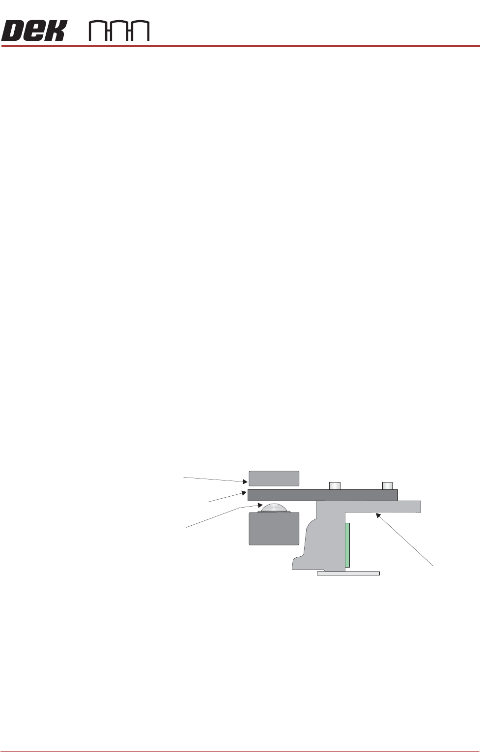
Chase
Chase Clamp
Roller Bearing
Roller Counter Plate
PRINTER PREPARATION
TRANSIT BRACKETS AND SCREWS REMOVAL
4.6 Installation Manual Chapter Issue 15, May 20
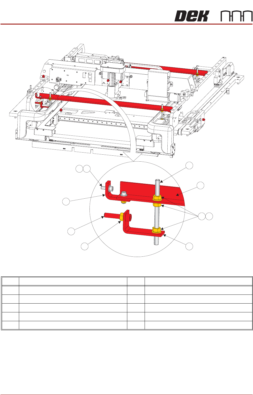
Figure 4-3 Front and Rear Transit Brackets
NOTE
Item 5, the Left Chase Transit Bracket is fitted upside down on dual lane
printers.
Item Description Item Description
1 M8 Chase Stud 6 Transit Adjustment Screw Lock Nut
2 Front/Rear Transit Bracket 7 Transit Adjustment Screw
3 M8 Nut 8 Adaptor Bracket
4 M8 Washer 9 M5 Cap Head Screw
5 Left Chase Transit Bracket 10 M5 Washer
9
1
2
3
4
5
6
7
8
10