88192278-01-19 Installation Master.pdf - 第127页
PRINTER PREPARATION PRINTER HEIGHT AND LEVELLING Chapter Issue 15, May 20 Installation Manual 4.25 27. Position the location block so contact is made with the locating collar on foot (3). 28. Fully tighten the fixing scr…

PRINTER PREPARATION
PRINTER HEIGHT AND LEVELLING
4.24 Installation Manual Chapter Issue 15, May 20
direction.
12. Move the engineering level along the centre row of screws running from front
to back.
13. Change the orientation of the Level and adjust the front centre mounting foot
(6) to level the printer in the Y direction.
14. Adjust the front centre mounting foot (6) to level the printer in the Y direction.
15. Repeat Steps 11 to 14 until the printer is level in both directions.
16. Carefully lower the front left mounting foot (1) so that it is in contact with the
floor.
17. Recheck the printer level has not been disturbed.
18. Carefully lower the front right mounting foot (2) so that it is in contact with
the floor.
19. Recheck the printer level has not been disturbed.
20. Lower the front centre mounting foot (6) so it is not in contact with the printer.
21. Remove the front centre mounting foot (6) and store in a safe place.
22. Tighten mounting feet locknuts.
23. Recheck the printer is level.
24. Recheck the printer height has not been disturbed.
25. Remove the engineering level from the printer.
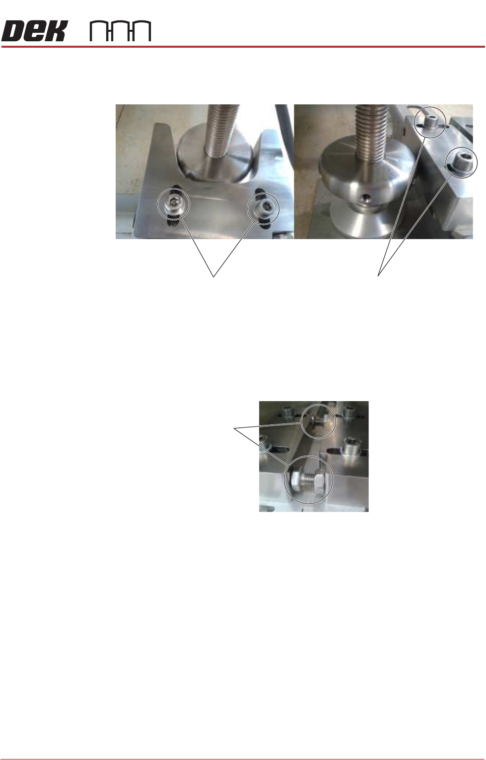
26. Position the V-block so contact is made with the locating collar on foot (4).
PRINTER PREPARATION
PRINTER HEIGHT AND LEVELLING
Chapter Issue 15, May 20 Installation Manual 4.25
27. Position the location block so contact is made with the locating collar on foot
(3).
28. Fully tighten the fixing screws securing both location blocks.
29. Position the locator blocks for printer B to achieve maximum adjustment,
and ensure parallel to the locator blocks for printer A.
30. Rotate the stopper bolts by hand until they make contact with the opposing
block, and then secure them using the locknuts.
31. Move printer A back into position locating foot (3) into V-Block.
32. Position locating foot (4) against Locating Block.
33. Recheck the printer is level.
34. Recheck the printer height has not been disturbed.
V-Block
Fixing Screws
Location-Block
Fixing Screws
Stopper Bolts
PRINTER PREPARATION
CHASE CLAMP CHECK
4.26 Installation Manual Chapter Issue 15, May 20
CHASE CLAMP CHECK
During transportation the chase clamps may have moved out of tolerance; this
can cause poor print results. The chase clamp gaps should be checked and
adjusted where necessary. In factory build, two shims were used as a Go/No
Go gauge to set the gap between the top of the roller counter plate and the
bottom of the clamp plate.
NOTE
Ensure that the printer height and level are set correctly before following this
procedure.
Using the Go/No Go shims check the gap on the left hand front clamp:
1. If the Go gauge cannot be inserted between the clamp plate and the roller
counter plate, go to Step 4.
2. If the Go gauge can be inserted between the clamp plate and the roller
counter plate but the No Go gauge cannot, go to Step 8.
3. If both gauges can be inserted into the gap, go to Step 4.
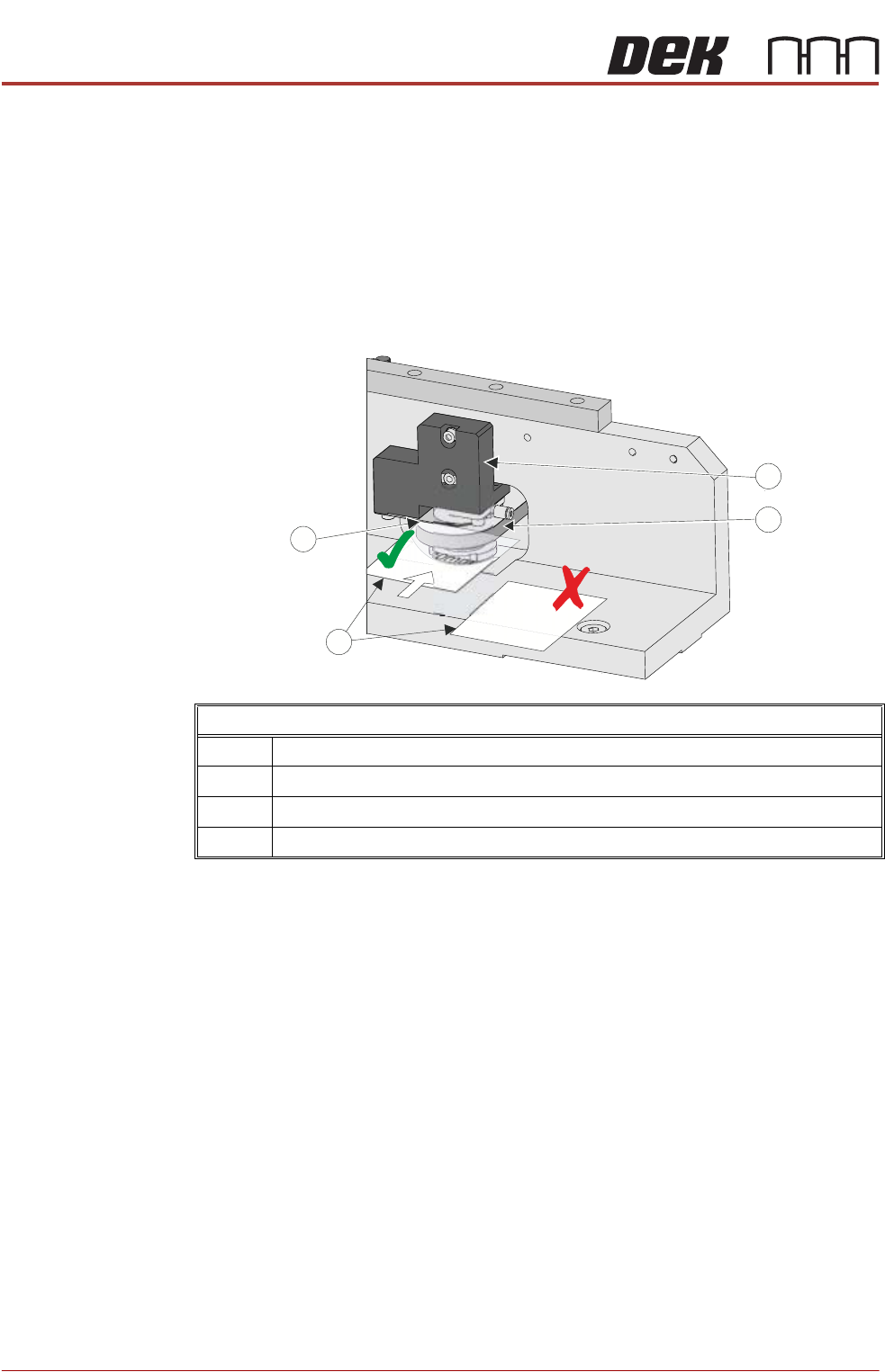
4. To adjust the clamp, using a 4mm Allen key, slacken off the two M5 cap
headed screws from the pneumatic block, to allow movement.
5. Move the pneumatic block up or down to achieve the gap in Step 2.
6. Using a torque wrench set to 5Nm tighten the screws ensuring the clamp
plate and roller counter plate remain parallel, and the gap is equal across
the width of these plates.
7. Recheck the gap.
8. Repeat the check for the right hand rear clamp.
Chase Clamp Gap Setting
1 Pneumatic Block
2 Roller Counter Plate
3 0.20mm Shim (GO) and 0.25mm Shim (No GO)
4Clamp Plate
PP
PP