88192278-01-19 Installation Master.pdf - 第156页
PRINTER PREPARATION PRINTER ASSEMBLY 4.54 Installation Manual Chapter Issue 15, May 20 Fit ProFlow A T x System Mount T o fit the ProFlow A Tx system mount to the printer , carry out the following procedure: 1. Locate th…
PRINTER PREPARATION
PRINTER ASSEMBLY
Chapter Issue 15, May 20 Installation Manual 4.53
ProFlow unit into the connector (9PL61) located on the left hand side of the
ProFlow, on the print carriage, figure in Step 7 refers.
NOTE
a. 1) An amplifier is connected to 9PL61 and the connection is made to
9PL62 on the amplifier.
b. 2) This electrical connection informs the printer of ProFlow fitment and
must always be connected whilst the ProFlow unit is fitted otherwise
damage may occur if printer is run.
Fitting ProFlow
ATx
To fit ProFlow ATx to the printer, carry out the following procedures:
• Fit ProFlow ATx System Mount
• Fit Transfer Head
• Level Transfer Head
• Fit Print Medium Cartridge
Mount Plate
PRINTER PREPARATION
PRINTER ASSEMBLY
4.54 Installation Manual Chapter Issue 15, May 20
Fit ProFlow ATx
System Mount
To fit the ProFlow ATx system mount to the printer, carry out the following
procedure:
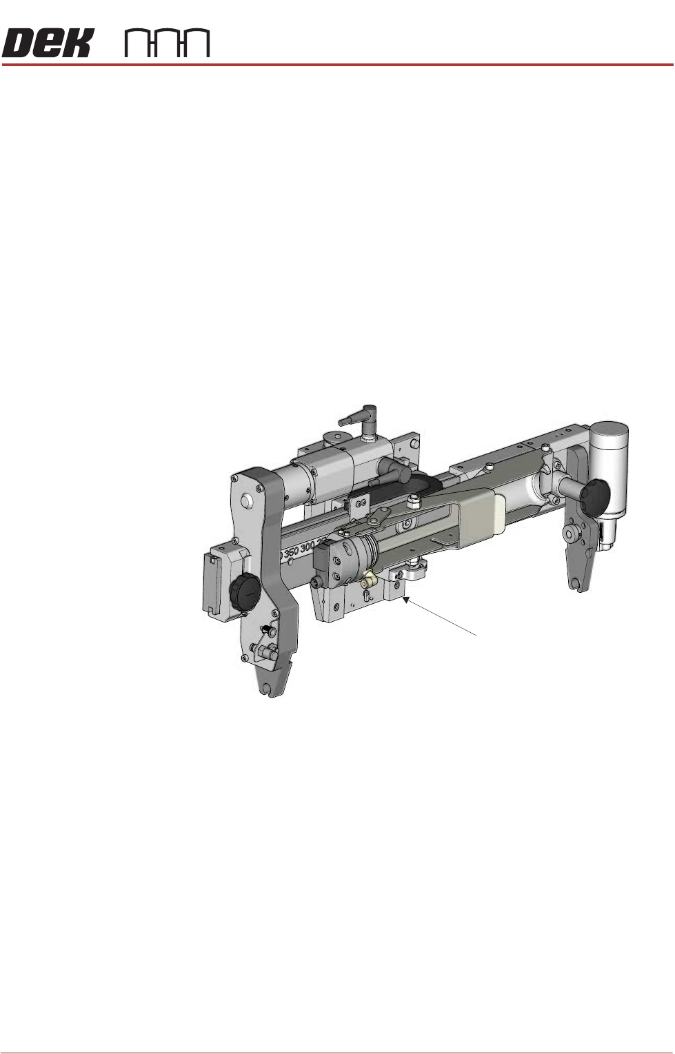
1. Locate the four captive mount screws and two locator dowels on the rear of
the mount plate of the ProFlow ATx system mount assembly.
2. Lower the ProFlow ATx system mount beam by manually turning the Z-axis
motor pulley counter-clockwise. This action reveals the four captive screw
heads located on the front face of the mount plate.
NOTE
The captive screws may be hidden behind the components on the front of
the mount assembly. Move the beam down until they are fully revealed.
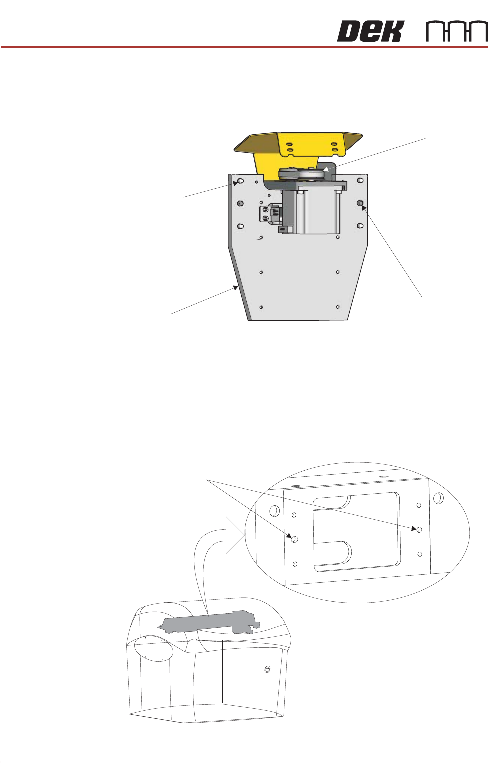
3. Locate the two locator dowel holes on the front face of the print carriage.
View on Rear of ProFlow Mount
Mount Plate
Captive Mount
Screw (4 Positions)
Locator Dowel
(2 Positions)
Z-Axis Motor
Pulley
Locator Dowel Holes
View on Front Left Corner
PRINTER PREPARATION
PRINTER ASSEMBLY
Chapter Issue 15, May 20 Installation Manual 4.55
4. Fit the ProFlow ATx system mount mechanism to the print carriage, ensuring
that both locating dowels fit into the locator dowel holes.
NOTE
Ensure the cables and air feed lines are free from moving parts that may
prevent the ProFlow ATx mount from being secured to the print carriage.
5. Secure the ProFlow ATx system mount to the print carriage; tighten the four
captive screws on the mount plate, using the 4mm T-bar Allen key supplied
(205973).
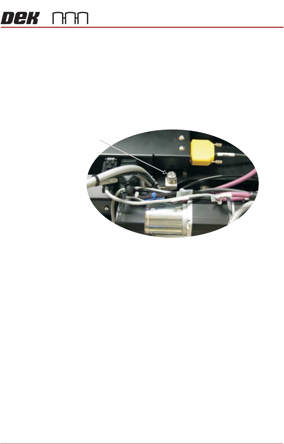
6. Using a crosshead screwdriver, attach the drag chain carrying the left hand
side cable and air feed connectors to the left hand side of the print carriage.
View on Print Carriage Top Face
Left Side Drag
Chain Screw