88192278-01-19 Installation Master.pdf - 第172页
PRINTER PREPARATION PRE POWER UP CHE CKS 4.70 Installation Manual Chapter Issue 15, May 20 a. Earth tag and the live output. b. Earth tag and the neutral output. c. Isolator mount and the neutral output. d. Isolator moun…
PRINTER PREPARATION
PRE POWER UP CHECKS
Chapter Issue 15, May 20 Installation Manual 4.69
PRE POWER UP CHECKS
Electrical Test Before the printer is connected to the factory electrical supply, the following
electrical tests must be performed:
1. Ensure the mains isolator switch is in the OFF position.
2. Remove the front cover of the printer to gain access to the mains isolator
switch.
3. Remove the front cover of the mains isolator switch.
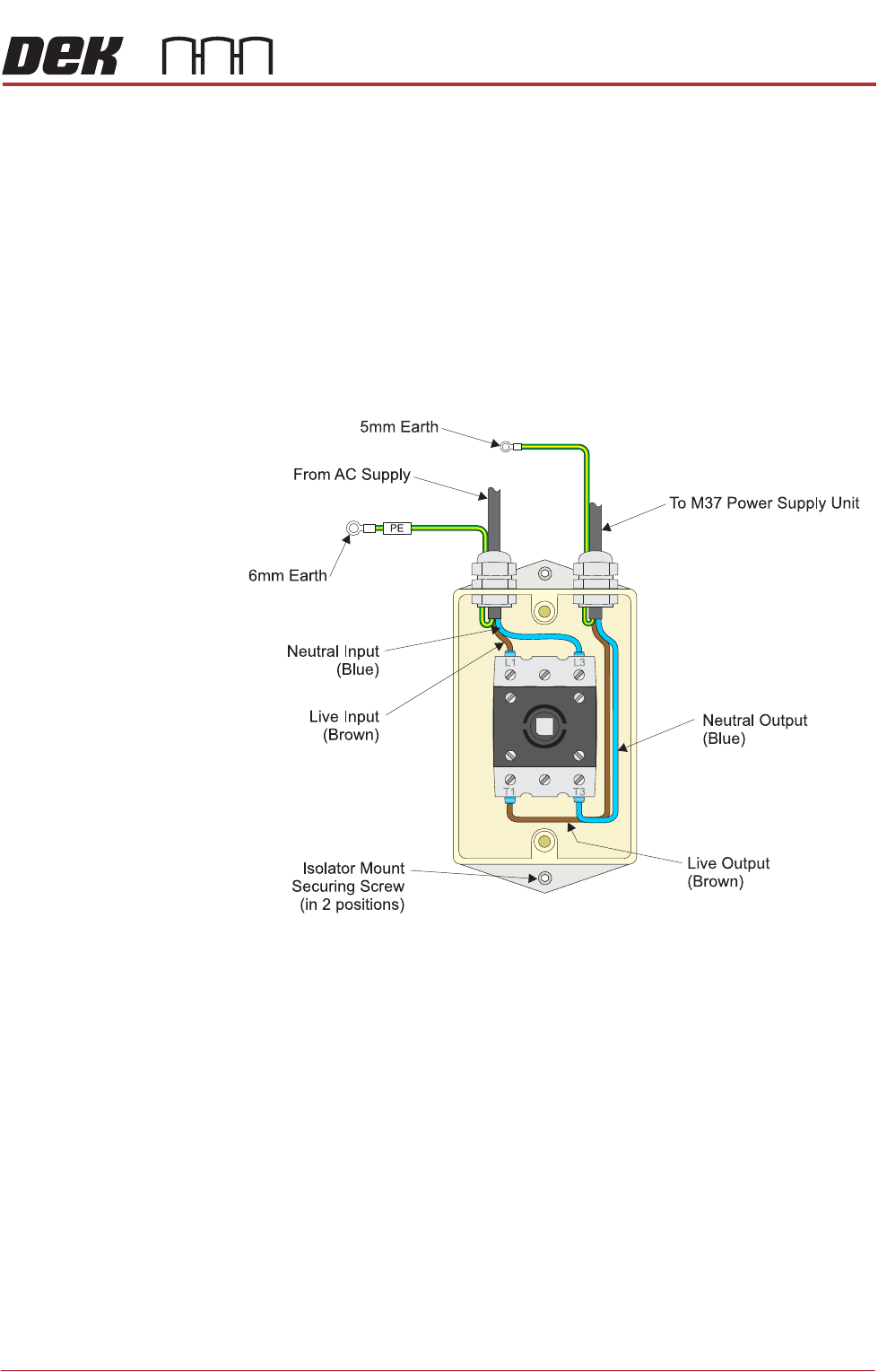
4. Perform a visual inspection of the mains isolator switch ensuring the
following:
a. The earth input and earth output cables are connected to the earth tag.
b. The live input is connected to the top of the isolator switch on the left hand
side.
c. The live output is connected to the bottom of the isolator switch on the left
hand side.
d. The neutral input is connected to the top of the isolator switch on the right
hand side.
e. The neutral output is connected to the bottom of the isolator switch on the
right hand side.
5. Ensure that all six cables are secure and no bare wires are showing.
6. Connect the two probes of a digital volt meter (DVM) together and ensure
that the DVM is reading 0Ω.
7. Measure the resistance between the following points ensuring that all the
measurements are greater than 2MΩ:

PRINTER PREPARATION
PRE POWER UP CHECKS
4.70 Installation Manual Chapter Issue 15, May 20
a. Earth tag and the live output.
b. Earth tag and the neutral output.
c. Isolator mount and the neutral output.
d. Isolator mount and the live output.
8. Measure the resistance between the earth tag and all three isolator mount
securing nuts ensuring that all measurements are less than 0.5Ω.
9. Remove the rear cover of the printer (front cover on type 4 printers).
10. Measure the resistance between the following points ensuring that all
measurements are less than 0.5Ω:
a. PC earth stud and a securing screw that secures the PC to the printer
frame.
b. M36 earth stud and a securing screw that secures the M36 to the printer
frame.
c. M37 earth stud and a securing screw that secures the M37 to the printer
frame.
11. Refit the mains isolator cover.
12. Refit the front cover.
13. Before refitting the rear cover, check the three circuit breakers on the M37
Power Supply Enclosure are in the ON position.
14. Refit the cover removed in Step 9.
Vacuum Filtration
Unit
There are four types of onboard vacuum filtration unit, for use with the under
screen cleaner, the VF25, the VF10 and the VF35i. The VF25 is a fixed voltage
unit at either 115V or 230V, ensure that the unit fitted matches the supply
voltage.
The onboard VF35i vacuum filtration unit is dual voltage 115V/230V (50Hz/
60Hz) switchable from the front panel of the unit.
PRINTER PREPARATION
PRE POWER UP CHECKS
Chapter Issue 15, May 20 Installation Manual 4.71
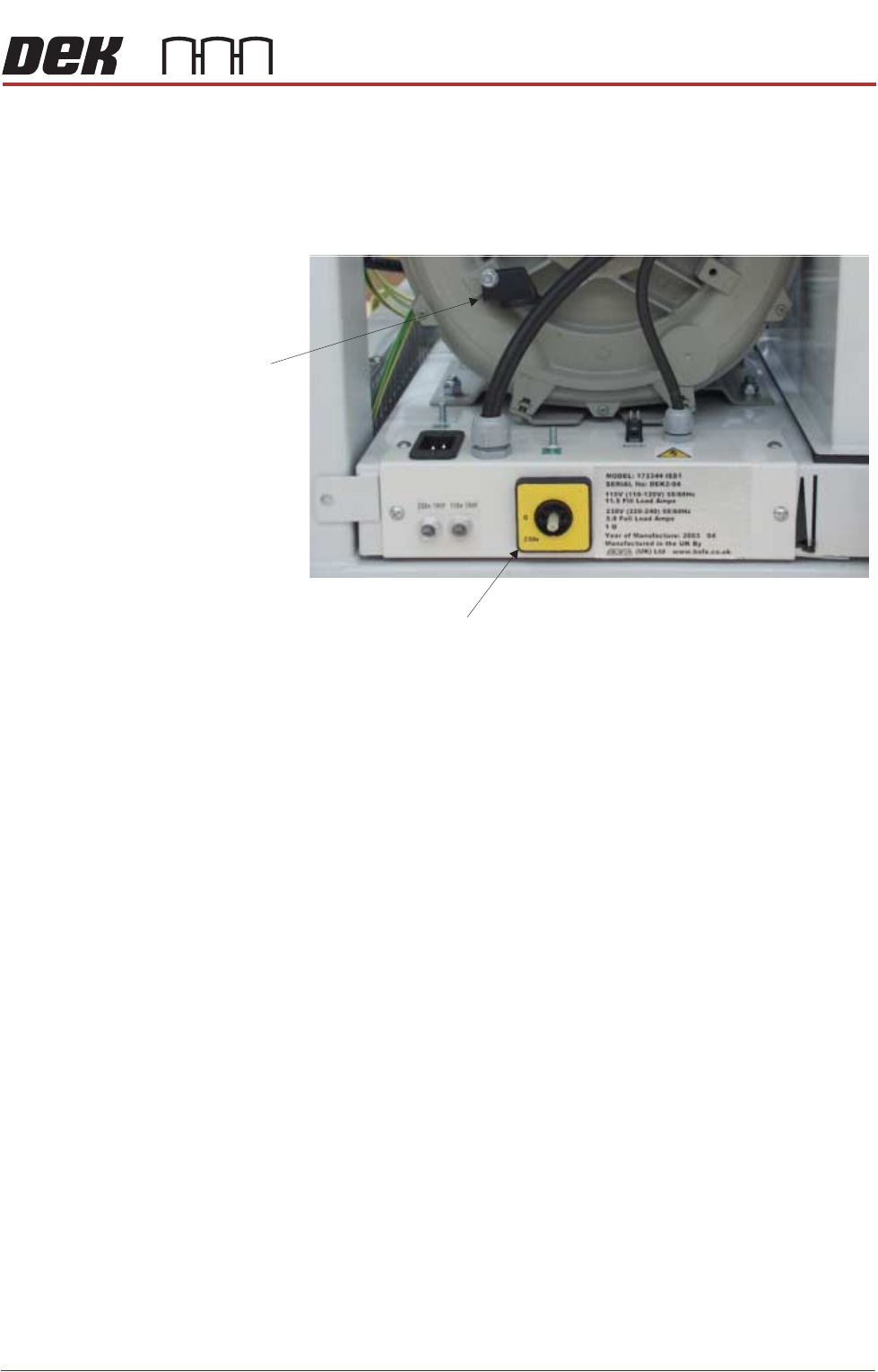
Ensure that the voltage selector switch, on the front panel of the onboard
vacuum filtration unit, is set to match the supply voltage. To check or switch the
voltage selector, carry out the following:
1. Using a 10mm spanner, remove the voltage selector control knob from the
fan housing.
2. Fit the voltage selector control knob to the voltage selector switch.
NOTE
The spindle has three keyways allowing the knob to be fitted in one position
only.
3. Ensure that the pointer of the knob is indicating the voltage that closely
matches the mains supply voltage.
NOTE
a. 1. This unit is liable to damage if the voltage selector does not match the
supply voltage.
b. 2. The ‘0’ position on the voltage selector is OFF disabling the vacuum
filtration unit.
4. Return the voltage selector control knob to the fan housing to prevent further
adjustment.
Voltage Selector Switch
Voltage
Selector
Control Knob
115v