88192278-01-19 Installation Master.pdf - 第110页
PRINTER PREPARATION TRANSIT BRACKETS AND SCREWS REMOVAL 4.8 Installation Manual Chapter Issue 15, May 20 10. Loosen the M8 nut (3) that secures the left chase transit bracket (5) to the chase on the front and rear tran s…
PRINTER PREPARATION
TRANSIT BRACKETS AND SCREWS REMOVAL
Chapter Issue 15, May 20 Installation Manual 4.7
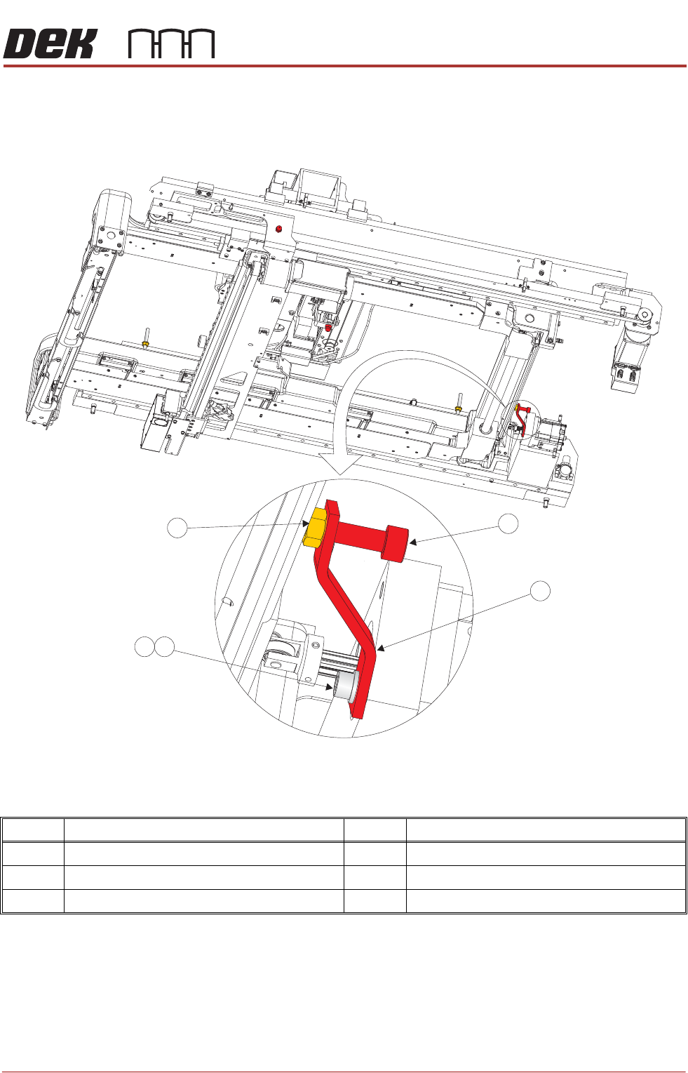
7. Loosen the transit adjustment screw lock nut (15) on the rear chase transit
bracket (12).
Figure 4-4 Rear Chase Transit Bracket
8. Using a 6mm Allen key, loosen the transit adjustment screw (7), on both the
left chase transit brackets (5), and the transit adjustment screw (11) on the
rear chase transit bracket (12), so that the chase comes into contact with
the three actuator shafts.
9. Using a 5mm Allen key, remove the rear chase transit bracket (12) by
removing the M6 cap head screw (13) and M6 washer (14).
Item Description Item Description
11 Transit Adjustment Screw 14 M6 Washer
12 Rear Chase Transit Bracket 15 Transit Adjustment Screw Lock Nut
13 M6 Cap Head Screw
View on Right Hand Underside
11
12
14
15
13
PRINTER PREPARATION
TRANSIT BRACKETS AND SCREWS REMOVAL
4.8 Installation Manual Chapter Issue 15, May 20
10. Loosen the M8 nut (3) that secures the left chase transit bracket (5) to the
chase on the front and rear transit brackets.
11. Unscrew the M8 chase studs (1) from the chase and remove from the
printer.
12. Remove the two left chase transit brackets (5) from the printer.
13. Remove the two right hand chase studs (1) by loosening the two M8 nuts
(3) that secure the chase studs (1) to the chase.
NOTE
1. The transit screws are constructed of a red plastic dome head nut and a
45mm steel grub screw. Although the two parts are bonded, ensure that both
parts are removed if they become separated.
2. When the printer has been levelled, and before printing, the chase clamps
should be checked to see if they have moved out of tolerance - refer to the
section - Chase Clamp Check for details.
Cover Frame
Transit Bracket
This transit bracket assembly is fitted to printers that have Anti-Vibration mounts
fitted to the covers frame.
Carry out the following procedure for removal:
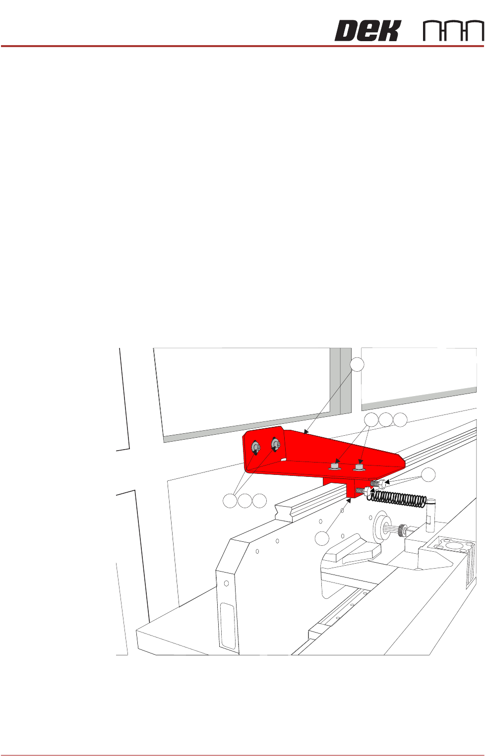
Figure 4-5 Cover Frame Transit Bracket
3
4
2
9
8
5
1
6
7
PRINTER PREPARATION
TRANSIT BRACKETS AND SCREWS REMOVAL
Chapter Issue 15, May 20 Installation Manual 4.9
1. Using a 4mm Allen key loosen the two M5 cap head screws (2), crinkle
washers (3) and washers (4) sufficiently to allow movement in the block (6).
2. Using a 10mm spanner loosen the M6 nylon screws (5) sufficiently to allow
the block to lift from the carriage rail, but do not remove.
3. Remove and retain the M5 cap head screws (7), crinkle washers (8) and
washers (9) using a 4mm Allen Key holding the bracket (1) to the covers
frame.
4. Remove the transit bracket (1) and block (6) as an assembly.
NOTE
After the transit bracket / block assembly has been removed, it is recommended
that the retained screws, crinkle washers and washers are refitted through the
neoprene washers on the covers frame and the previously loosened screws on
the assembly are tightened to prevent loss.
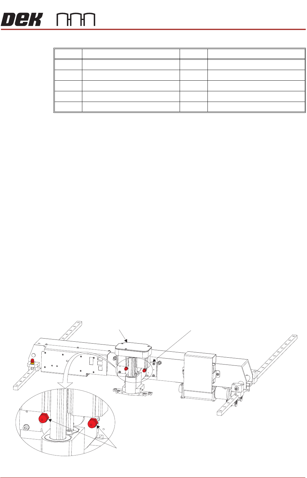
Transit Screws
Squeegee Transit
Screws
1. Snip the cable ties securing the piece of card to the front of the squeegee
mechanism. Remove the cable ties and the piece of card from the printer.
2. Whilst supporting the squeegee mechanism, remove the two squeegee
transit screws.
Item Description Item Description
1 Cover Frame Transit Bracket 6 Block
2 M5 Cap Head Screw 7 M5 Cap Head Screw
3 M5 Crinkle Washer 8 M5 Crinkle Washer
4M5 Washer 9M5 Washer
5 M6 Nylon Screw
Squeegee Transit Screws
Squeegee Mechanism Squeegee Mount