88192278-01-19 Installation Master.pdf - 第197页
HIGH THROUGHPUT CONVEYOR (HTC) OPERATION Chapter Issue 6, May 20 Installation Manual 6.7 2. Place a second board clamp setting plate onto the transport belts of the print station. 3. Ensure the plates abut and are full y…
HIGH THROUGHPUT CONVEYOR (HTC)
OPERATION
6.6 Installation Manual Chapter Issue 6, May 20
1. Using a Board Clamp Setting Plate Part No. 88140403-01, place the plate
on the right hand auxiliary conveyor transport belts.
2. Place a 0.5mm feeler gauge between the plate and the inner face of the
auxiliary conveyor rear rail.
3. Run the feeler gauge along the whole length of the conveyor rail, the fit of
the feeler gauge should be tight, between the plate and the inner face of the
rail.
4. Remove the feeler gauge and manually move the plate in and out of the
machine along the conveyor transport belts, ensuring the plate moves freely
without binding or jamming.
5. If adjustment is required, carry out the following: loosen the two rear rail
securing bolts, adjust the rail to achieve parallelism and re-tightening the rail
securing bolts.
6. Repeat Steps 2 to 5 to re-check for parallelism.
7. Repeat Steps 1 to 6 for the left hand auxiliary conveyor.
Auxiliary Conveyor
Height Setting
To check and if required adjust the height of the auxiliary conveyor to the print
station rails carry out the following at transport height:
NOTE
Before continuing with this procedure refer to the Pre-Power Up section of this
chapter. Check the integrity of the machine power connections before connect-
ing the printer and powering it up. Ensure that all transport brackets have been
removed prior to powering up. Use diagnostics to lift the transport rails to
transport height.
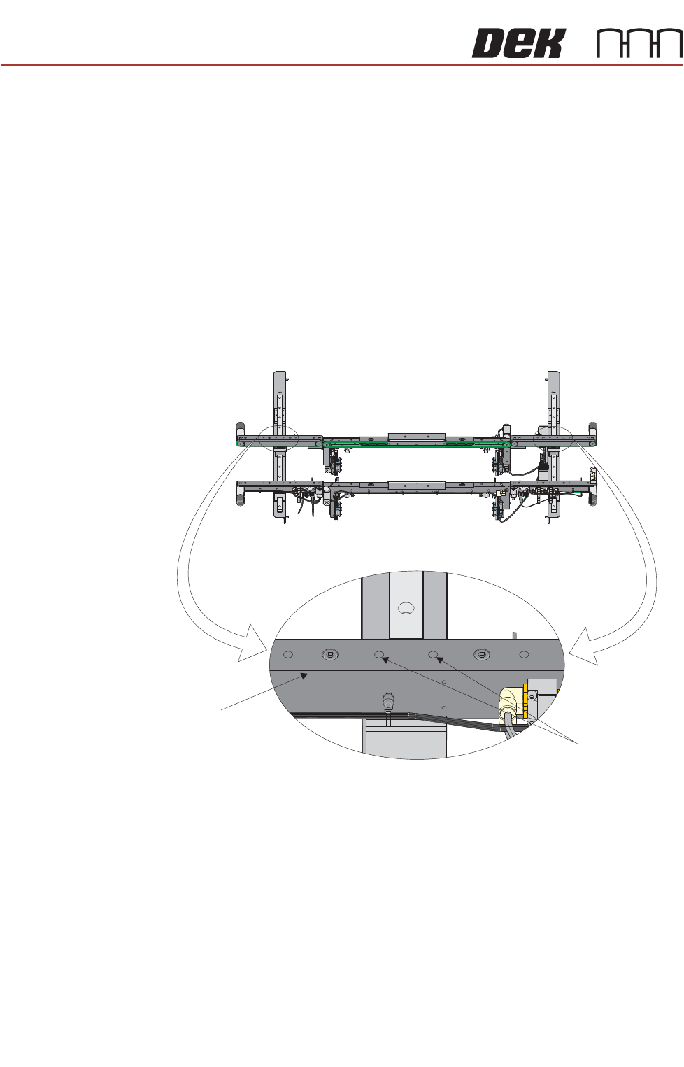
1. Using a Board Clamp Setting Plate Part No. 88140403-01, place the plate
on the auxiliary conveyor transport belts.
Front View of HTC Rails
Auxiliary Conveyor
Rear Rail
Rear Rail
Securing Bolts
HIGH THROUGHPUT CONVEYOR (HTC)
OPERATION
Chapter Issue 6, May 20 Installation Manual 6.7
2. Place a second board clamp setting plate onto the transport belts of the print
station.
3. Ensure the plates abut and are fully supported by the transport belts.
4. Using a spirit level, place across both setting plates and check the plates
are level.
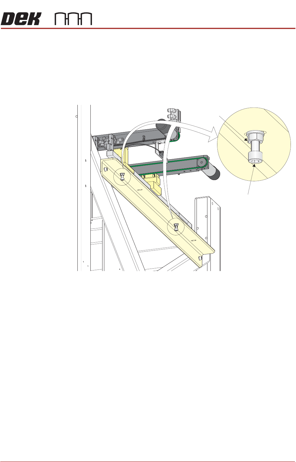
5. If adjustment is required, loosen the locking nuts on the two auxiliary
conveyor height adjustment bolts.
6. To alter the height of the conveyor carefully adjust both height adjustment
bolts.
7. Carefully adjust the height of the conveyor rails until they match the print
station rails.
8. Re-tighten the locking nuts loosened in Step 5 and repeat the check.
9. If adjustment has occurred, carry out Auxiliary Conveyor Levelling check.
10. Fit the side covers and panels that were previously removed.
Auxiliary Conveyor
Height Adjustment
Bolt
Locking Nut

HIGH THROUGHPUT CONVEYOR (HTC)
OPERATION
6.8 Installation Manual Chapter Issue 6, May 20