88192278-01-19 Installation Master.pdf - 第175页
PRINTER PREPARATION PRE POWER UP CHECKS Chapter Issue 15, May 20 Installation Manual 4.73 T ype 4 Printers In order for the printer to fu nction correctly the following services must be available: • Pneumatic Supply • El…
PRINTER PREPARATION
PRE POWER UP CHECKS
4.72 Installation Manual Chapter Issue 15, May 20
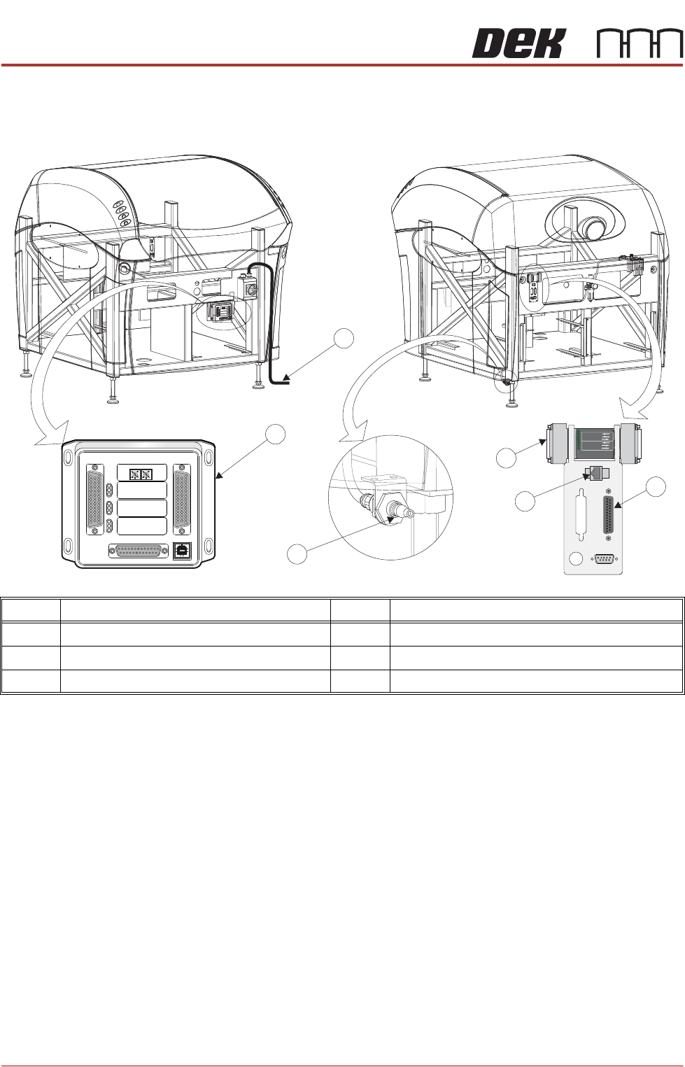
External Services
Type 1, 2, 3 and 5 printers
In order for the printer to function correctly the following services must be
available:
• Pneumatic Supply
• Electrical Supply
Other services that may be required are:
• Host Communications
• Upline/Downline Machine Interface (FMI/MIU)
• Temperature Control Module (TCM)
Item Description Item Description
1 Printer Mains Supply Cable 4 Foreign Machine Interface (FMI) Pod
2 Temperature Control Module (TCM) 5 Air Connection
3 Host Comms LAN RJ45 6 Multi Interface Unit (MIU)
M
1
S
K
1
M
1
S
K
1
U
PL
I
N
E
UP
LI
NE
M1
SK
2
M1
SK
2
D
O
W
N
LI
NE
D
O
W
NLI
N
E
M
1P
L3
M1PL3
D
E
K
M
/
C
DEK
M
/C
M
1
S
K
4
M
1S
K
4
D
E
K
U
SB
DEK
U
S
B
+1
2
V+
1
2
V
+2
4
V
+24
V
+2
4V SW
+24
V
SW
S
E
N
D
U
P
L
I
NE
S
END UP
LI
N
E
S
E
N
D
DOW
N
LINE
S
E
N
D
DO
WN
L
IN
E
CO
NTRO
L
I
N
CO
N
T
R
OLI
N
UP
L
I
N
E
R
E
AD
YUP
L
I
NE REA
D
Y
DO
W
N
LI
N
E
R
EAD
Y
DO
W
N
L
INE R
E
A
D
Y
C
ONTRO
L
OUT
C
O
NTR
OL
OU
T
P
O
WE
R
P
OWER
I
/P'
SI
/P'
S
O
/P
'SO
/
P'
S
P
RO
T
OC
O
L
S
EL
EC
T
IO
N
P
R
O
TOC
OL
SE
L
E
CTIO
N
U
P
U
P
L
I
N
E
L
I
N
E
DO
WN
DOWN
LIN
E
LINE
M
IU
1
9
1
11
4
MI
U
191114
4
8
0
4
8
0
POWER ON
PART No. 160740
M/C AVAILABLE
BOARD AVAILABLE
BOARD PASS
D
O
W
N
LIN
E
BOARD AVAILABLE
BOARD PASS
M/C AVAILABLE
U
P
LIN
E
FMI POD
View on RearView on Front
1
2
3
4
5
6
M1SK1
UPLINE
M1SK2
DOWNLINE
M1PL3
DEK M/C
M1SK4
DEK USB
+12V
+24V
+24V SW
SEND UPLINE
SEND DOWNLINE
CONTROL IN
UPLINE READY
DOWNLINE READY
CONTROL OUT
POWER
I/P'S
O/P'S
PROTOCOL SELECTION
UP
LINE
DOWN
LINE
MIU 191114
4
80
4
80
PRINTER PREPARATION
PRE POWER UP CHECKS
Chapter Issue 15, May 20 Installation Manual 4.73
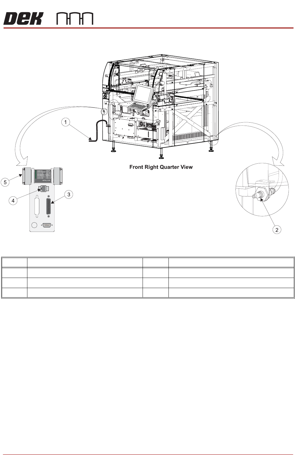
Type 4 Printers
In order for the printer to function correctly the following services must be
available:
• Pneumatic Supply
• Electrical Supply
Other services that may be required are:
• Host Communications
• Upline/Downline Machine Interface (FMI)
• Temperature Control Module (TCM)
Item Description Item Description
1 Printer Mains Supply Cable 4 Host Comms LAN RJ45
2 Air Connection 5 Foreign Machine Interface (FMI) Pod
3 Temperature Control Module (TCM)
PRINTER PREPARATION
PRE POWER UP CHECKS
4.74 Installation Manual Chapter Issue 15, May 20
Pneumatic Supply The printer requires a pneumatic supply of clean, non lubricated air which
should maintain a minimum pressure 5 Bar and a maximum of 8 Bar.
The air should be to ISO 8573.1 standard, quality class 2.3.3, where:
• 2 dirt = 1 micron
• 3 water = -20°C pressure dew-point
• 3 oil = 1mg/m³
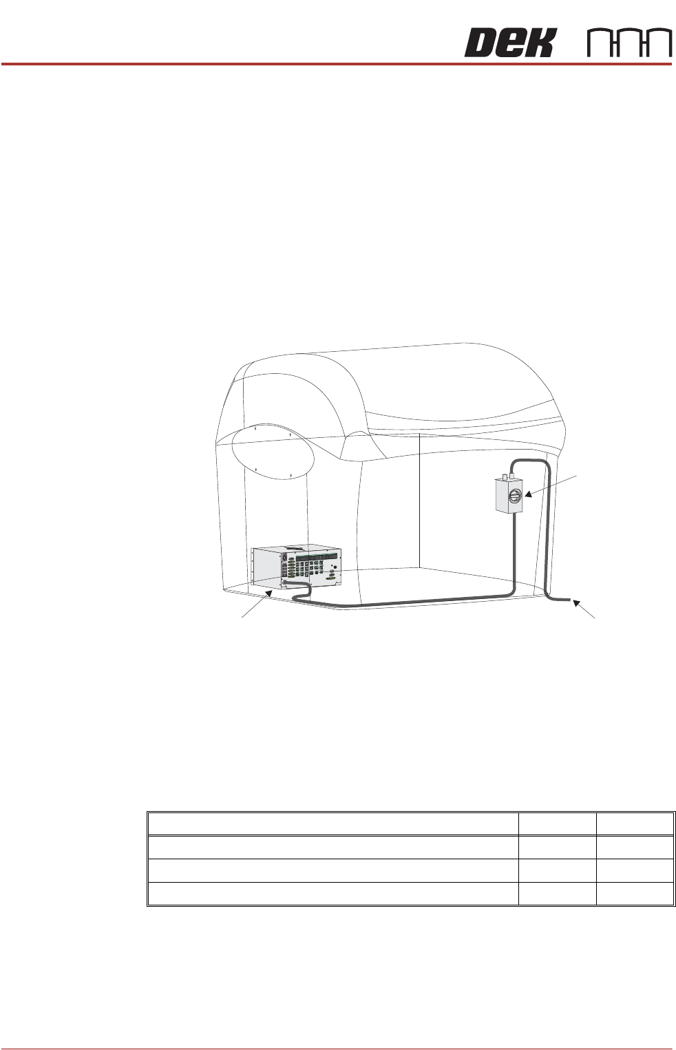
Electrical Supply The factory mains supply for the printer is routed through the front panel
mounted mains isolator switch and on to the M37 power supply enclosure where
various low voltages are distributed throughout the printer.
Figure 3-1 Mains Electrical Supply
The printer operates on 115V to 230V ± 10% 50/60Hz single phase AC mains.
ASM recommends a power supply capacity of 2.4KVA or greater.
ASM requires additional printer supply protection with the fitment of an external
double pole circuit breaker conforming to national, federal or local legislation.
Use the following table to ensure the recommended circuit breaker is used:
NOTE
An over current circuit breaker protects the printers internal wiring and
components from overheating or catching fire during fault conditions. Under no
circumstances must a circuit breaker of value greater than 20 Amps be fitted.
115 Volts 230 Volts
Wall Mounted Type C Circuit Breaker (without Vacuum Unit) 10 Amp 6 Amp
Wall Mounted Type C Circuit Breaker (with VF25 Vacuum Unit) 16 Amp 10 Amp
Wall Mounted Type C Circuit Breaker (with VF30/355 Vacuum Unit) 16 Amp 10 Amp
To Factory Mains Supply
Mains Isolator
Switch
M37 Power Supply Enclosure