D-serie level 1 EN.pdf - 第121页
P&P and TWIN Heads Preparations for Component Pickup (Modul e 2) TWIN Head Pickup and Place Cycle S tude nt Guide Advanced Level 1 SIPLACE D-Series EN 05/2007 P&P and TWIN Heads 7-7 7.2.3 Prep arations for Co mpo…
P&P and TWIN Heads
TWIN Head Pickup and Place Cycle Preparations for Component Pickup (Module1)
Student Guide Advanced Level 1 SIPLACE D-Series
P&P and TWIN Heads EN 05/2007
7-6
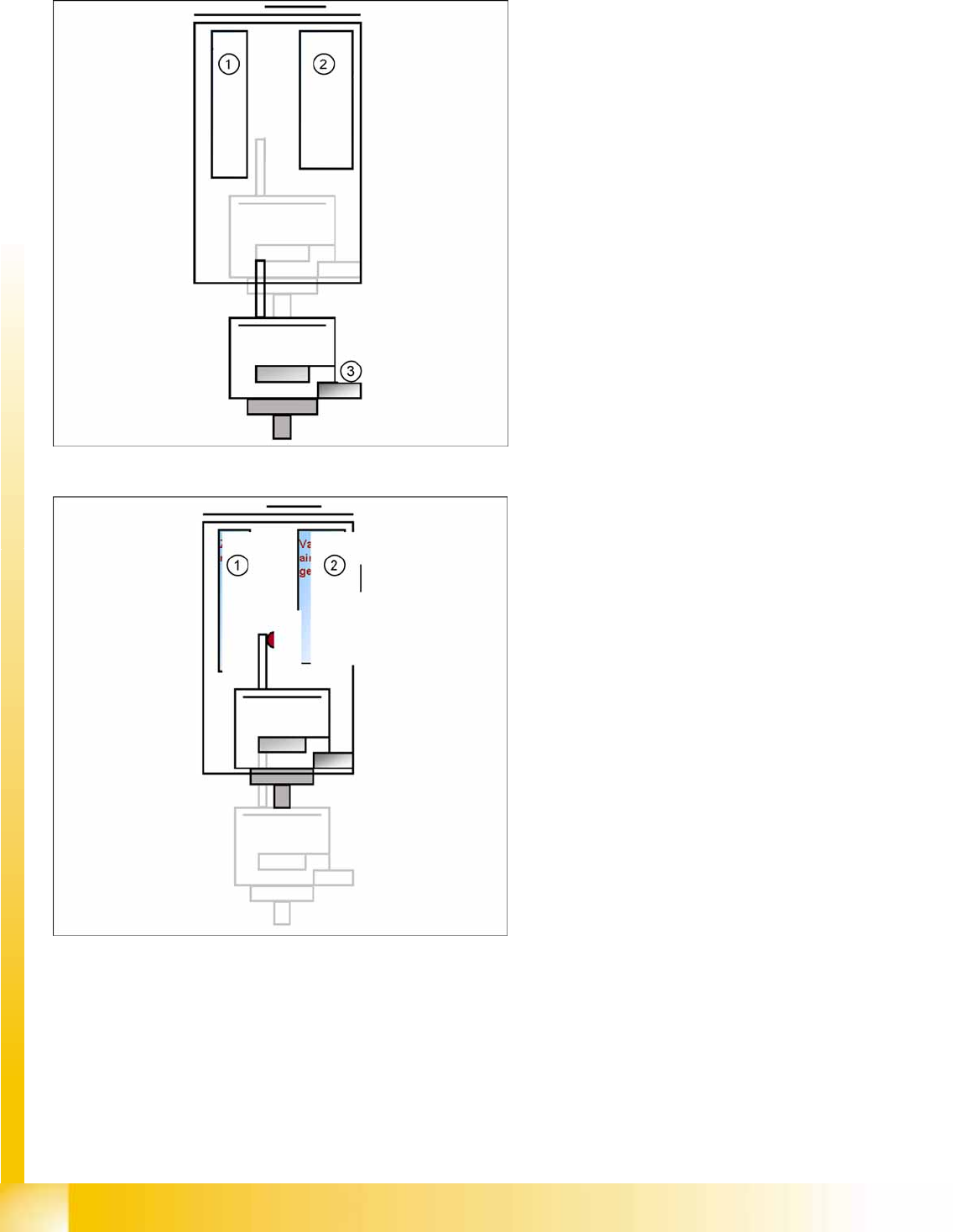
7.2.2.1 Component Pickup (Module 1)
Legend
1. Z-motor
2. Vacuum/air blast generator
3. Force sensor
Z-axis moves downwards with standard mode
(2 N pickup force).
On contact with the component, the force
increases to the programmed value.
When this value is reached, the end signal is
triggered and the vacuum check is activated.
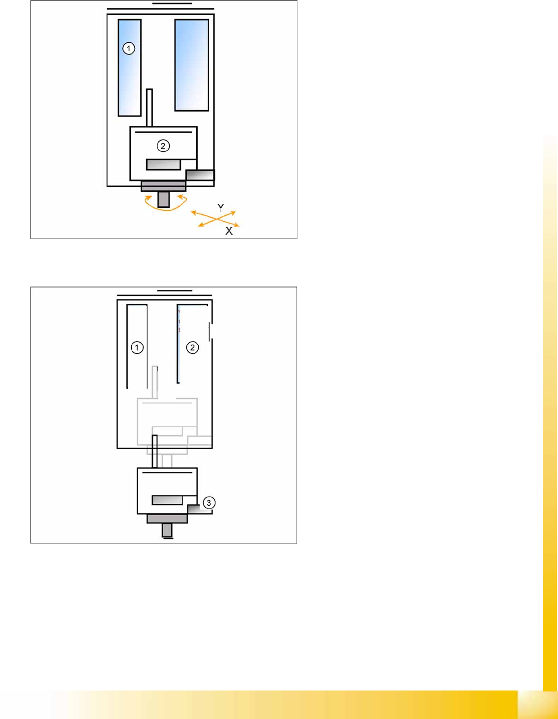
Legend
1. Z-motor
2. Vacuum/air blast generator
The Z-axis moves upwards with standard
travel mode.
Communication with component trolley -
continue feeder cycle - as soon as the Z-axis
position "safety height" is reached.
When the Z-axis up end signal is emitted, the
"component on nozzle" vacuum check is
performed.
The D-axis is rotated to the placement angle
(so that only the component correction angle
needs to be rotated after centering).
Preparation for continued pickup (component
on module 2).
P&P and TWIN Heads
Preparations for Component Pickup (Module 2) TWIN Head Pickup and Place Cycle
Student Guide Advanced Level 1 SIPLACE D-Series
EN 05/2007 P&P and TWIN Heads
7-7
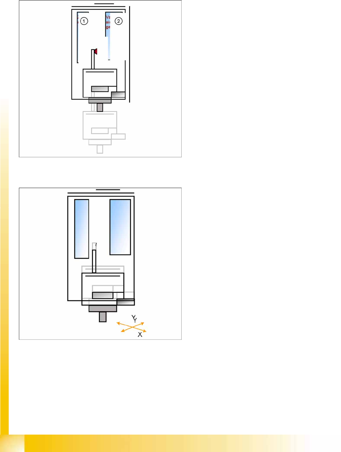
7.2.3 Preparations for Component Pickup (Module 2)
7.2.3.1 Component Pickup (Module 2)
Legend
1. Z-motor
2. D motor
Pick up with module 1 is finished.
The X and Y gantry axes move to the feeder
track or pickup position.
During gantry positioning, the D-axis of
module 2 moves to the pickup angle.
Communication with component trolley -
feeder ready - opens the feeder pickup
window.
Legend
1. Z-motor
2. Vacuum/air blast generator
3. Force sensor
Z-axis moves downwards with standard mode
(2 N pickup force).
On contact with the component, the force
increases to the programmed value.
When this value is reached, the end signal is
triggered and the vacuum check is activated.
P&P and TWIN Heads
TWIN Head Pickup and Place Cycle Preparations for Placement (Module 1 Component)
Student Guide Advanced Level 1 SIPLACE D-Series
P&P and TWIN Heads EN 05/2007
7-8
7.2.4 Preparations for Placement (Module 1 Component)
Legend
1. Z-motor
2. Vacuum/air blast generator
When the vacuum threshold ‘Pickup’ is
reached, the Z-axis moves upwards with
standard travel mode.
Communication with component trolley -
continue feeder cycle - as soon as the Z-axis
position "safety height" is reached.
When the Z-axis up end signal is emitted, the
"component on nozzle" vacuum check is
performed.
The D-axis is rotated to the placement angle
(so that only the component correction angle
needs to be rotated after centering).
The preparations are performed for optical
centering of the component at module 1.
The X/Y gantry axes move to the corrected
placement position.
The D-axis rotates by the placement angle
correction value.