D-serie level 1 EN.pdf - 第123页
P&P and TWIN Heads Preparations for Placement (Module 1 C omponent) TWIN Head Pickup and Place Cycle S tude nt Guide Advanced Level 1 SIPLACE D-Series EN 05/2007 P&P and TWIN Heads 7-9 7.2.4.1 Placement (Module 1…
P&P and TWIN Heads
TWIN Head Pickup and Place Cycle Preparations for Placement (Module 1 Component)
Student Guide Advanced Level 1 SIPLACE D-Series
P&P and TWIN Heads EN 05/2007
7-8
7.2.4 Preparations for Placement (Module 1 Component)
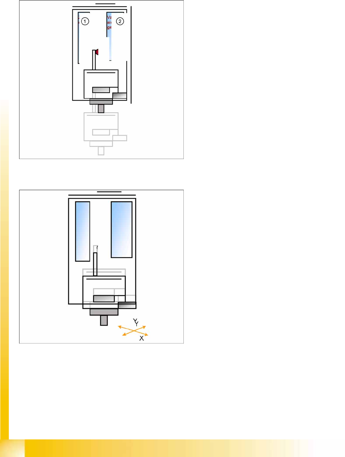
Legend
1. Z-motor
2. Vacuum/air blast generator
When the vacuum threshold ‘Pickup’ is
reached, the Z-axis moves upwards with
standard travel mode.
Communication with component trolley -
continue feeder cycle - as soon as the Z-axis
position "safety height" is reached.
When the Z-axis up end signal is emitted, the
"component on nozzle" vacuum check is
performed.
The D-axis is rotated to the placement angle
(so that only the component correction angle
needs to be rotated after centering).
The preparations are performed for optical
centering of the component at module 1.
The X/Y gantry axes move to the corrected
placement position.
The D-axis rotates by the placement angle
correction value.
P&P and TWIN Heads
Preparations for Placement (Module 1 Component) TWIN Head Pickup and Place Cycle
Student Guide Advanced Level 1 SIPLACE D-Series
EN 05/2007 P&P and TWIN Heads
7-9
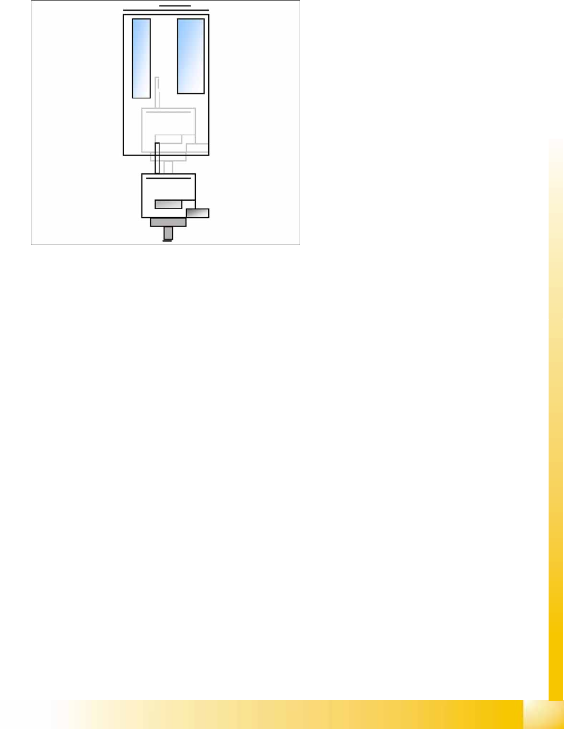
7.2.4.1 Placement (Module 1 Component)
The Z-axis moves downwards in standard
mode (2 N contact force).
The contact force increases to the
programmed level when placing the
component onto the PCB.
When this value is reached, the end signal is
triggered and the air blast control is activated.
When the air blast threshold* is reached, the
Z-axis moves upwards with the standard travel
profile.
Preparations for further placement
(component at module 2).
P&P and TWIN Heads
P&P Head Main Board Preparations for Placement (Module 1 Component)
Student Guide Advanced Level 1 SIPLACE D-Series
P&P and TWIN Heads EN 05/2007
7-10
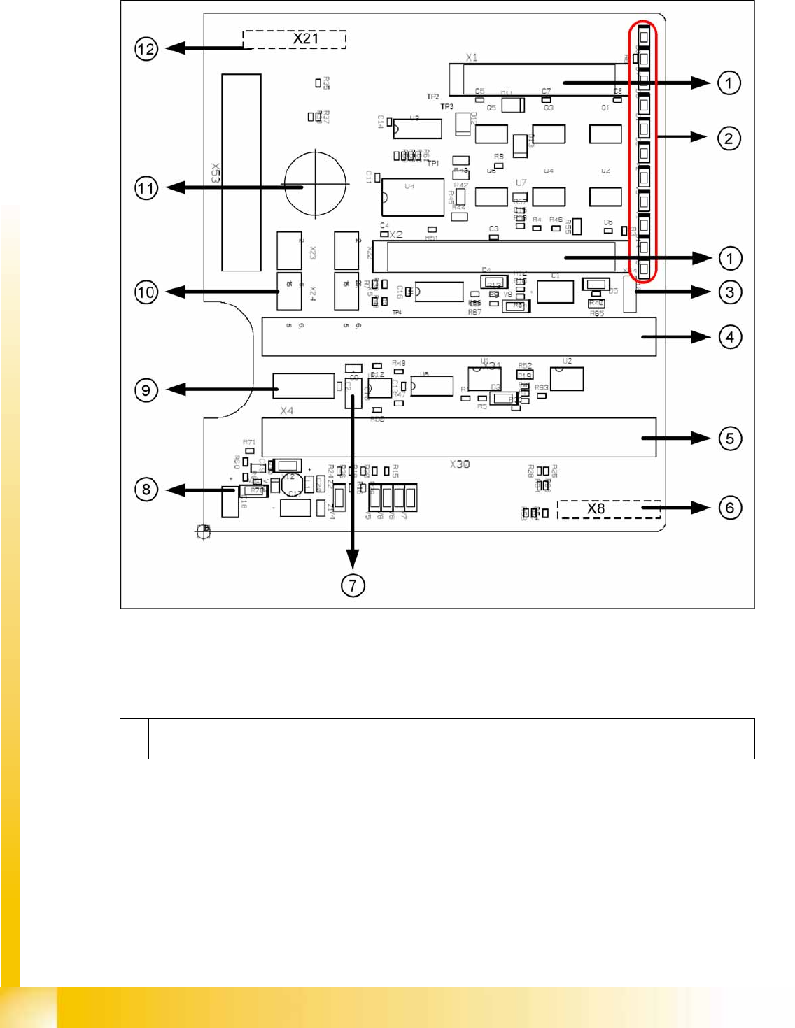
7.3 P&P Head Main Board
7-4: P&P head main board [00352833-xx]
Legend
The main board is mounted directly on the P&P head. This board is connected to the head adapter board
via two flat ribbon cables.
1 2 connectors for the 16 bit CAN Bus processor (not
used for X/D1/D3)
7 EEPROM storage the head specific data ( Head
exchange, Reference run)