D-serie level 1 EN.pdf - 第28页
Overview Machine Overview Comparison D1 to D4 SIPLACE D4 Configuration S tuden t Guide Advanced Level 1 SIPLACE D-Series Overview EN 05/2007 3-4 3.2 Machine Overview Comp arison D1 to D4 Designation D4 D3 D2 D1 D1 single…
Overview
SIPLACE D4 Configuration General
Student Guide Advanced Level 1 SIPLACE D-Series
EN 05/2007 Overview
3-3
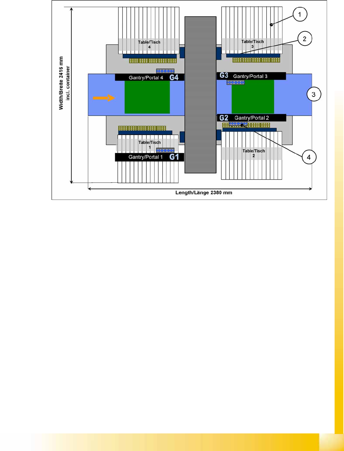
3.1.2 SIPLACE D4 Configuration
3-2: SIPLACE D4 configuration
Legend
1. S-table with S-feeder
2. Reject container for components and nozzles, without sensor for the reject container
3. Single/dual conveyor with stationary side on left or right
4. 4x C&P12
Overview
Machine Overview Comparison D1 to D4 SIPLACE D4 Configuration
Student Guide Advanced Level 1 SIPLACE D-Series
Overview EN 05/2007
3-4
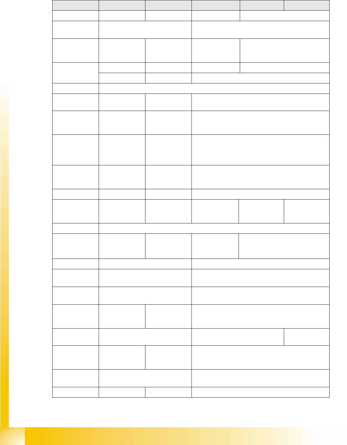
3.2 Machine Overview Comparison D1 to D4
Designation D4 D3 D2 D1 D1 single head
Succeeds HS50/60 ---- S2X FX
Processing
areas
21
SMEMA height
increases
3 distance plates
(70, 100,
120 mm)
2 distance plates
(70, 100/120,
mm)
3 distance plates
(70, 100, 120 mm)
3 distance plates (70, 100, 120 mm)
Gantries 432 1
Cast gantry CFK gantry Extended cast gantry
Y drive Linear motor
X-drive Motor with belt
drive
Linear motor Motor with belt drive
Y-motor cooling Through
compressed air
supply
Through motor
generating
compressed air
Through compressed air supply
X-motor cooling Through fan
during
component
pickup
Through exhaust
from C&P/TWIN
heads
Through fan during component pickup
X-axis board Gantry head
distributor,
version 3
Head interface/
adapter
Gantry head distributor, version 3
Y-axis board Gantry distributor Gantry interface Gantry distributor
Placement head
type
C&P -12 C&P12/6 PA1 /
C&P12/6 / TWIN
PA2
C&P 12/6 C&P12/6 and
P&P ( = 1 TWIN
seg.)
C&P12/6 or
P&P
(= 1 TWINseg.)
C&P version DLM3
Max.
component
height
6 mm C&P12 6 mm/
C&P6 8.5 mm/
TWIN 25 mm
C&P12 6 mm/
C&P6 8.5 mm
C&P12 6 mm/C&P6 8.5 mm/ P&P
19 mm
Conveyor 5 part 3 part
Conveyor
control
TSP 301 TSP 201
For dual
conveyor
With extension board Without extension board
SC Box PC Currently with
computer rack or
box PC
Box PC
Basic software SC/MC602 SC/MC603.01 SC/MC603.01
SP1
MC Micro Box PC
+ USB DVD-LW
MC slot PC
(C086) or BoxPC
+ USB DVD-LW
Micro Box PC
+ USB DVD-LW
MC operating
system
602 RMOS/603 WinXP 603 WinXP
USB hub 7-fold 4-fold 7-fold (or 4-fold)
Overview
SIPLACE D4 Configuration Machine Overview Comparison D1 to D4
Student Guide Advanced Level 1 SIPLACE D-Series
EN 05/2007 Overview
3-5
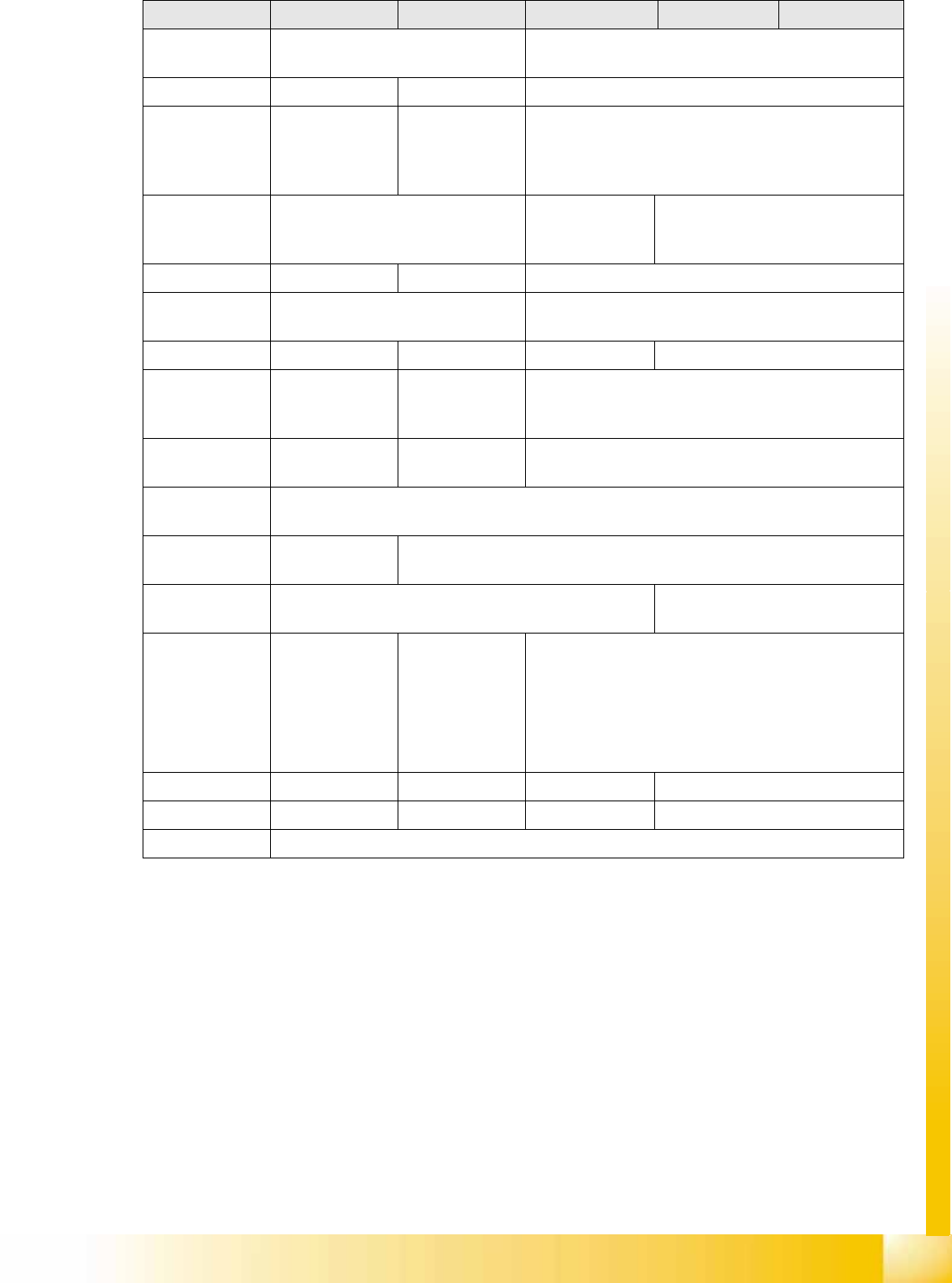
Axis controller
rack
2 racks with code switch 1 rack with code switch to standard
Axis controller A 364 A363/A364 A 364
Pneumatic
changeover
table docking
unit
--- YES ---
No. changeover
table positions
per location
1 each STP 2 / STP1 pos
for D2
STP 1 pos D2 or D1
(Pos. D1 22 mm further inside)
Cutter HS version HF version New extended HS
Changeover
table S feeder
HF version New, widened
Head modularity --- C&P12/6/TWIN C&P12/6 C&P12/6 with P&P
Placement
head/servo
parts
No Same as X
machine
C&P and P&P module
HM parts kit for
head assembly
No --- Set for D-series
HM parts kit for
servos and NC
YES
Camera
modularity
SST28/SST29/
SST38
SST28/SST29/SST38 for C&P12
(additionally P&P at D1: SST36, SST33 and SST25 optional)
Temperature
compensation I
Both gantries in the placement area (PA) check the PCB
position.
The PCB camera checks the IC/FC
camera position at defined intervals.
Temperature
compensation II
Temperature
sensor at C&P
gantries
Temperature
sensors on C&P
gantry/ TWIN IC/
FC camera
position - check
at defined
intervals.
Temperature sensor at C&P gantries
FlipChip camera --- YES --- YES
Coplan ILD 2200 --- YES --- YES
GEM option ---
Designation D4 D3 D2 D1 D1 single head