D-serie level 1 EN.pdf - 第25页
Overview General S tude nt Guide Advanced Level 1 SIPLACE D-Series EN 05/2007 Overview 3-1 3 Overview Unless othe rwise specifie d, the over view is based on the exa mple of a D4 m achine. 3.1 General The high-spe ed SIP…

Operational Safety
Room for Your Sketches and Notes Dispatching ESD Assemblies
Student Guide Advanced Level 1 SIPLACE D-Series
Operational Safety EN 05/2007
2-10
Overview
General
Student Guide Advanced Level 1 SIPLACE D-Series
EN 05/2007 Overview
3-1
3 Overview
Unless otherwise specified, the overview is based on the example of a D4 machine.
3.1 General
The high-speed SIPLACE D4 placement machine combines high placement performance with accuracy
and flexibility. The machines use the Collect&Place placement method.
The SIPLACE D4 placement machine is equipped with four gantries, for fast and accurate positioning
along the X and Y axes.
Each gantry has a 12-segment C&P head (C&P12). Each placement area is served by two gantries:
Placement area 1 Gantries 1 and 4
Placement area 2 Gantries 2 and 3
The components are optically centered with the help of a digital Vision module. Two different component
cameras are available for the placement heads: a standard camera and a high-resolution component
camera.
A five-segment PCB conveyor, consisting of input conveyor, processing conveyor 1, intermediate
conveyor, processing conveyor 2 and output conveyor, transports the components to the processing
positions. PCB transport can be performed with a single or flexible dual conveyor (with stationary side
either on the left or right). A PCB camera is used to optically center the boards.
See also:
J 1.2 SIPLACE on the World Wide Web (WWW) [J1-3]
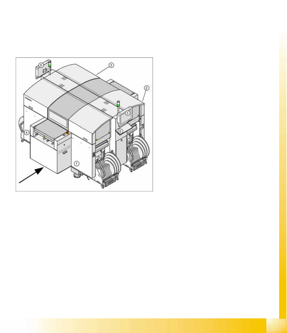
3-1: SIPLACE D4 placement machine
Legend
1. Sector 1
2. Sector 2
3. Sector 3
4. Sector 4
5. Monitor (on both sides)
6. Keyboard (on both sides)

Overview
General Specifications
Student Guide Advanced Level 1 SIPLACE D-Series
Overview EN 05/2007
3-2
3.1.1 Specifications
3.1.1.1 SIPLACE D4 Specifications - Excerpt
NOTE: D-series training CD and download center
The specifications for all machine types can be found on the training CD or in the download
center of your SIPLACE user group You will also find operating manuals, maintenance
instructions and other documentation there.
Types of placement head 12-segment Collect&Place head (C&P12)
Number of gantries 4
Placement performance (benchmark
test)
60.000 components/h with SC/MC 602
66.000 components/h with SC/MC 603
Placement positions 3,500 / gantry
Range of components
0.6 x 0.3 mm
2
(0201) to 18.7 x 18.7 mm
2
Max. component height 6 mm
Placement accuracy / angle accuracy Camera type 28: ± 60 µm, ± 0.5° (3 s), ± 80 µm, ± 0.7° (4 s)
Camera type 29: ± 60 µm, ± 0.5° (3 s), ± 80 µm, ± 0.7° (4 s)
Component feeding 4 component trolleys with tape reel holder and integrated waste
containers (12 locations à 30 mm width per component trolley)
Feeder module types Tape, bulkcase, stick magazines, application-specific OEM feeder
modules, surftape feeder modules (8, 12, 16 mm), waffle pack trays
Feeding capacity 48 tape feeder modules 3 x 8 mm S (144 tracks)
48 tape feeder modules 2 x 8 mm S (96 tracks)
48 tape feeder modules x 12/16 mm S (48 tracks)
32 tape feeder modules x 24/32 mm S (32 tracks)
PCB format
(LxW)
Single conveyor
50 x 50 mm
2
to 368 x 460 mm
2
50 x 110 mm
2
to 610 x 460 mm
2
(option "Long board")
Width up to 508 mm on request
Dual conveyor
50 x 50 mm
2
to 368 x 216 mm
2
50 x 110 mm
2
to 610 x 216 mm
2
(option "Long board")
Width up to 242 mm on request
Dual conveyor in Single conveyor mode
50 x 50 mm
2
to 368 x 380 mm
2
50 x 110 mm
2
to 610 x 380 mm
2
(option "Long board")
Width up to 430 mm on request
PCB thickness 0.3 to 4.5 mm (thicker PCBs available on request)