D-serie level 1 EN.pdf - 第86页
C&P6/12 Placement Heads Overview C&P Head Placement Construction S tuden t Guide Advanced Level 1 SIPLACE D-Series C&P6/12 Placement Heads EN 05/2007 6-6 6.1.5.3 Camera Modularity 6.1.5.4 Focus Level of C&…

C&P6/12 Placement Heads
C&P Head Placement Construction Overview
Student Guide Advanced Level 1 SIPLACE D-Series
EN 05/2007 C&P6/12 Placement Heads
6-5
6.1.5 C&P Head Placement Construction
6.1.5.1 Hardware - New Features for C&P Head
The D4 does not have a Head Modularity function, as this machine is designed to succeed the HS, as a
fast placement machine for small components.
The placement heads on the D-series have the following common/different features:
6.1.5.2 Placement Head Differences Between DLM 2/1 and DLM3
Assembly D4 D3 D2 D1
C&P head types C&P12 C&P12 or 6 C&P12 or 6 C&P12 or 6
Star drive ‚C28’
03031187-01
New bearings / strengthened motor shaft / green heat-shrinkable sleeve for star axis
incremental encoder cable
Forced air unit 00367793-02 new version 02: with date printed on the e-valve
DP station 00341780-05 version 5, downwards compatibility
Valve positioning
drives
Version 2
Requirements Minimum 601.03 SP1 or A364 axis controller
Head modularity No Same as X machines Reconfig. set C&P12
head 00119860-01
Reconfig. set C&P6
head 00119861-01
Special features Component sensor fasteners for C&P12 with 130Ncm
Hardware - new features for C&P head
Assembly DLM 1/2 DLM 3
C&P head type C&P12 & 6 C&P12 or 6
Placement star drive
‚C28’ 03031187-01
New bearings / stronger motor shaft / green
heat-shrinkable sleeve for star axis
incremental encoder cable New machine
data for star axis
Placement star drive
‚C29’
Compatible fitting for DLM1 and 2
New forced air unit Downwards
compatibility
YES
DP station 00341780-05 version 5, downwards compatibility
Valve positioning
drive
Version with original cam disk DLM1 / new
cam disk DLM2
DLM2 cam disk and version 2
Requirements Minimum SC/MC 601.03 SP1 or A364 axis
controller
Special features Component sensor fasteners for C&P12 with 130Ncm
Placement head differences between DLM 2/1 and DLM3
C&P6/12 Placement Heads
Overview C&P Head Placement Construction
Student Guide Advanced Level 1 SIPLACE D-Series
C&P6/12 Placement Heads EN 05/2007
6-6
6.1.5.3 Camera Modularity
6.1.5.4 Focus Level of C&P Component Camera
6.1.5.5 Nozzle Changer Features
Camera D4
with C&P12
D3
with C&P12
D2
with C&P12
D1
with C&P12
Standard C&P12 SST28 SST28 SST28 SST28
As high-resolution
version
SST29 SST29 SST29 SST29
Camera D3
with C&P6
D2
with C&P6
D1
with C&P6
Standard C&P6 --- SST29 SST29 SST29
Camera equipment for C&P head options
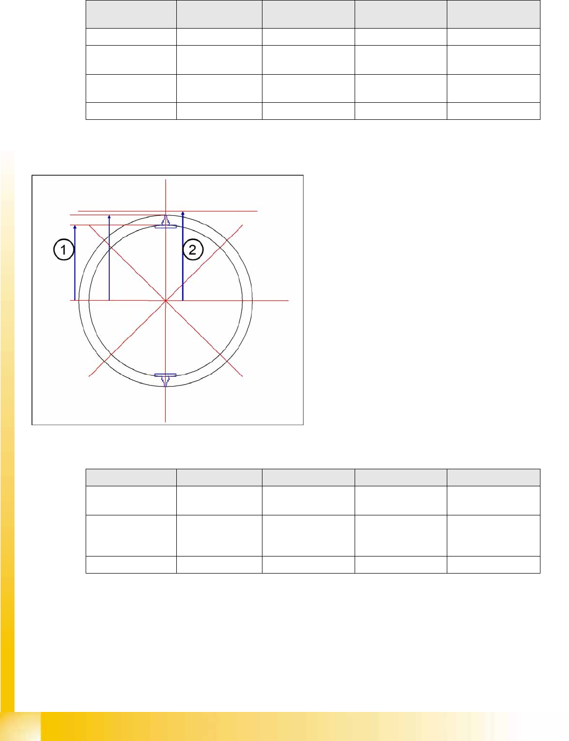
The digital component camera has a pixel size
correction function in case the calculated
component level deviates too greatly from the
theoretical focus level.
If the “placement head radius (1) plus nozzle
length plus component height“ data deviates from
the theoretical focus level (2), an appropriate
correction pixel size factor is derived from this.
Features for C&P12 D4 D3 D2 D1
Number of NC
carriers per gantry
1 HS compatible 2 X compatible 1 new 1 new
Number of
magazines per
carrier
55 5 5
Supply pressure 5 bar 2.5 bar 2.5 bar 2.5 bar
NC features for C&P placement head
C&P6/12 Placement Heads
C&P Head Placement Construction Overview
Student Guide Advanced Level 1 SIPLACE D-Series
EN 05/2007 C&P6/12 Placement Heads
6-7
6.1.5.6 Nozzle Changer for 12 Segment C&P Head
Optionally, a nozzle changer can be installed for each C&P head. This enables the nozzle configuration
to be changed quickly, thus allowing the Collect&Place head to be quickly adapted to the needs of the
placement process.
The nozzle changer consists of at least one and up to five magazines, each of which is equipped with
up to twelve nozzle garages. The magazines are seated on a common support and each magazine is
centered using two pins and is fixed in place with a spring hook.
Each garage can be configured with different nozzle types.
Features for C&P6
head
D4 D3 D2 D1
Number of NC
carriers per gantry
--- 2 X compatible 1 new 1 new
Number of
magazines per
carrier
--- 6 6 6
Length of NC carrier
(outer edges)
475 mm 450 mm 565 mm 565 mm
Features for C&P12 D4 D3 D2 D1
NC features for C&P placement head
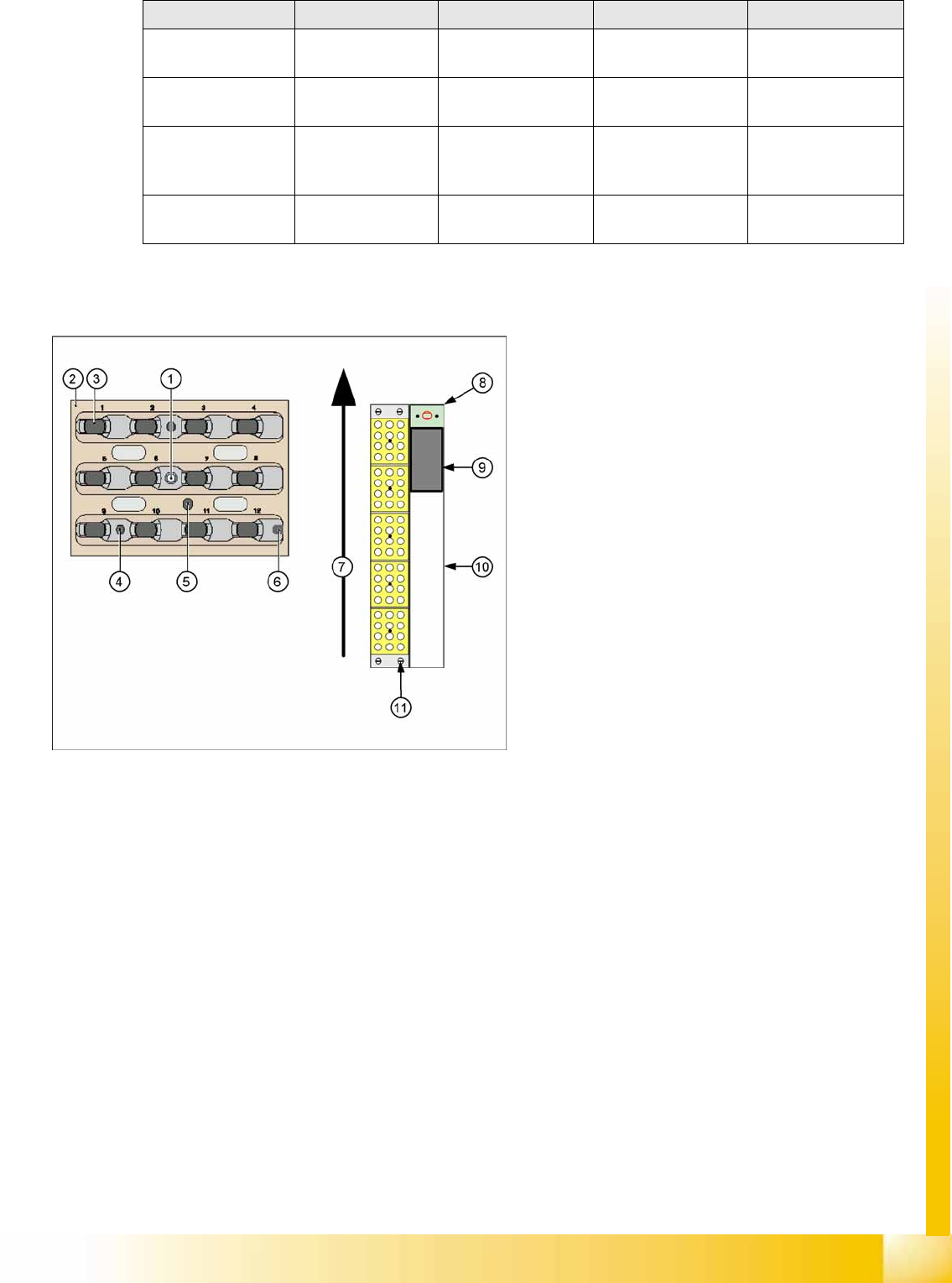
6-4: Nozzle changer and nozzle magazine for C&P12 (D4 shown as
example)
Legend
1. Calibration fiducial on magazine
2. Locking plate
3. Nozzle garage
4. Hole for centering pin, for exact positioning of
magazine
5. Hole for driver pin, for opening and closing of
magazine
6. Slit for centering pin, for exact positioning of
magazine
7. Transport direction
8. Nozzle reject device
9. Nozzle reject container
10. Tape duct
11. Fastening screws for nozzle changer (4x)