D-serie level 1 EN.pdf - 第98页
C&P6/12 Placement Heads Placement Procedure Picking up Component 9 S tuden t Guide Advanced Level 1 SIPLACE D-Series C&P6/12 Placement Heads EN 05/2007 6-18 6.2.10 Picking up Component 9 6.2.1 1 Recognition of Co…
C&P6/12 Placement Heads
Picking up Component 7 Placement Procedure
Student Guide Advanced Level 1 SIPLACE D-Series
EN 05/2007 C&P6/12 Placement Heads
6-17
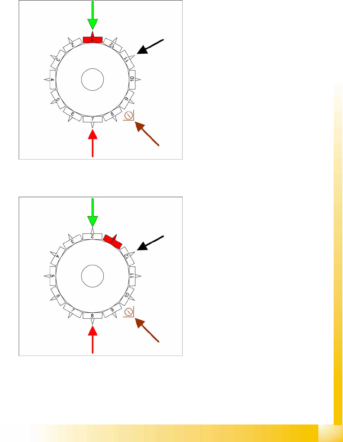
6.2.8 Picking up Component 7
6.2.9 Picking up Component 8
6-18: Picking up component 7
Star position 180°
Vision system: component at segment 1 is
measured
DP station rotation of nozzle 11 to its pickup
angle
Pickup/placement station: Pick up the
component 7
Component sensor: during the next star step,
the length of nozzle 9 is measured.
6-19: Picking up component 8
Star position 210°
Vision system: Component at segment 2 of
this gantry is centered
DP station rotation of nozzle 12 to its pickup
angle
Pickup/placement station: Pick up the
component 8
Component sensor: during the next star step,
the nozzle length is measured at segment 10.
C&P6/12 Placement Heads
Placement Procedure Picking up Component 9
Student Guide Advanced Level 1 SIPLACE D-Series
C&P6/12 Placement Heads EN 05/2007
6-18
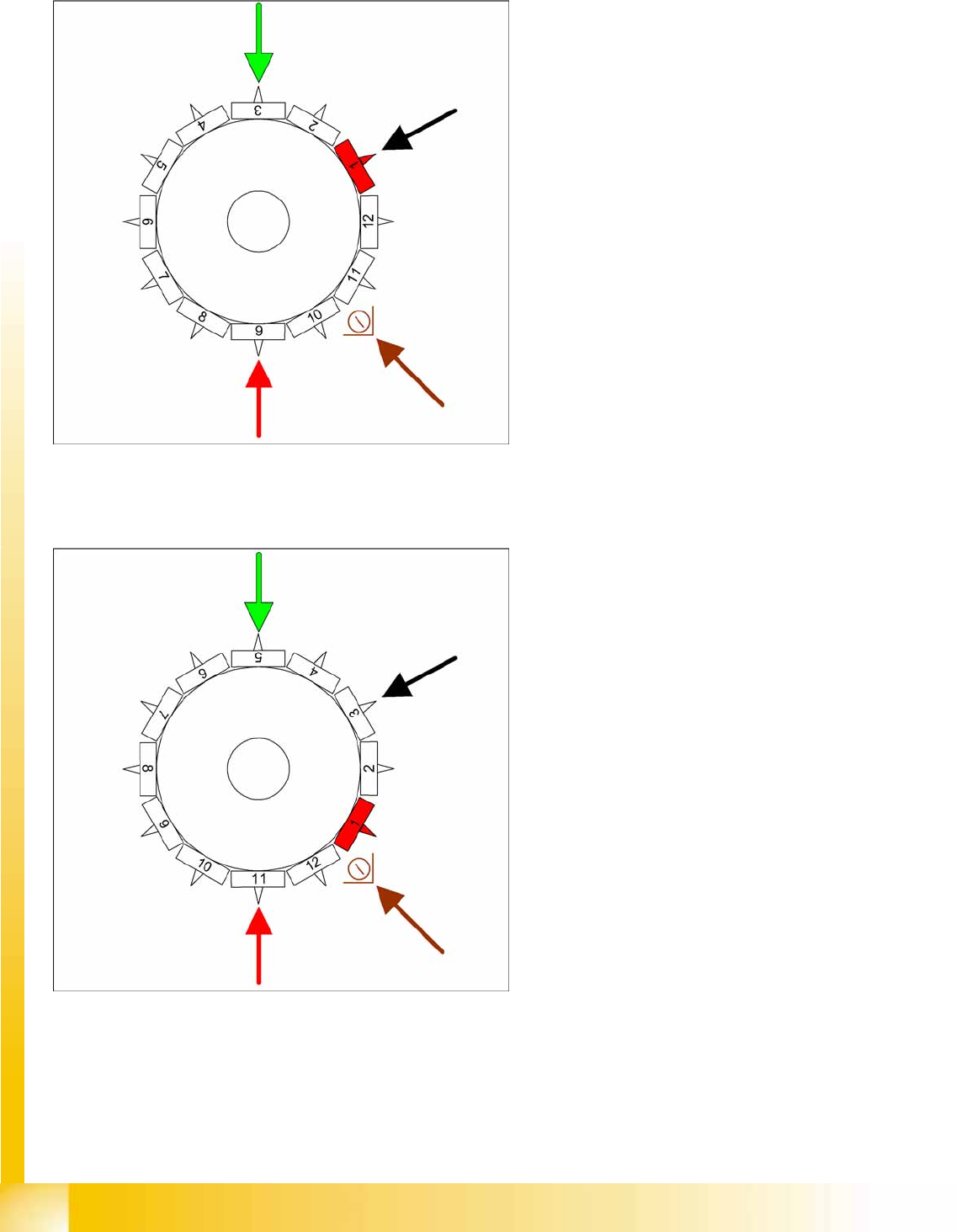
6.2.10 Picking up Component 9
6.2.11 Recognition of Component at Segment 1 in the Component Sensor
6-20: Picking up component 9
Star position 240°
Vision system: optical centering of component
3
DP station rotation of component 1 into its
exact placement angle
Pickup/placement station: Pick up the
component 9
Component sensor: during the next star step,
the nozzle length is measured at segment 11.
The process continues with the remaining
components: pickup, center and rotate into the
corrected placement angle.
6-21: Recognition of component at segment 1 in the component sensor
Star rotates -> 330°
Measurement by the component sensor
(optional): While the star axis rotates to position
330.000 digits:
The component sensor checks the presence
or the component height at segment 1.
Depending on the operating mode, the
component sensor measurement must adhere
to the following limits:
– Component presence check: The
measured length before placement must
exceed
nozzle length + component
height - component height tolerance
.
– Component height check: The measured
value must be between
nozzle length when empty + compo-
nent height - component height tole-
rance
and
nozzle length when empty + compo-
nent height + component height tole-
rance
.
Measurement is performed "On the Fly".
C&P6/12 Placement Heads
Picking Up Component 12 Placement Procedure
Student Guide Advanced Level 1 SIPLACE D-Series
EN 05/2007 C&P6/12 Placement Heads
6-19
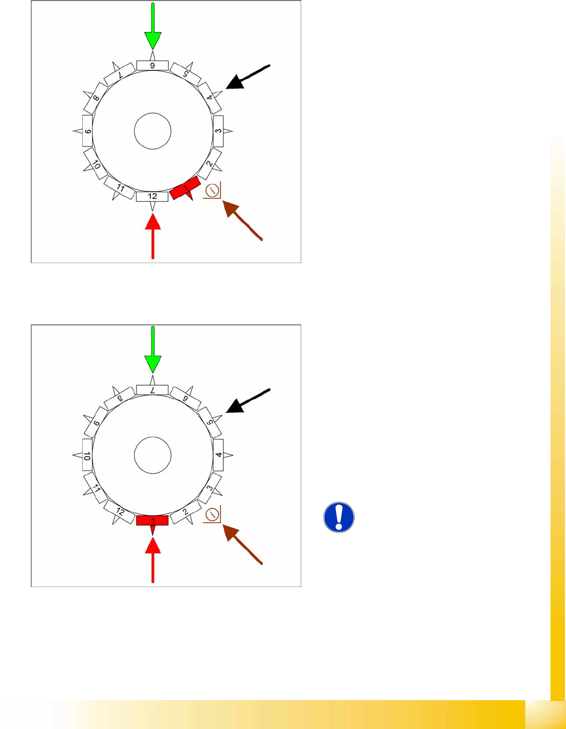
6.2.12 Picking Up Component 12
6.2.13 Placing Component 1
6-22: Picking up component 12
Star position 330°
Vision system: Optically centers component 6.
DP station: Rotates component 4 into its exact
placement angle.
Pickup/placement station: Picks up
component 12.
Communication with the changeover table:
Activate cutter.
Component sensor: During the next star cycle,
the component presence/component height
check is performed for segment 2.
6-23: Placing component 1
Star position 0°
Vision system: Optically centers component 7.
DP station: Rotates component 5 into its exact
placement angle.
Pickup/placement station: Places component
1.
Component sensor: During the next star cycle,
the component presence/component height
check is performed for segment 3.
This process is continued for the remaining
nozzles.
NOTE:
The machine learns a real placement
height for each placement position.This
is why placement of the first 15 or so
boards is significantly slower than
calculated by the setup optimization.