D-serie level 1 EN.pdf - 第135页
Component Handling Docking and Undocking the Changeover Table Overview S tude nt Guide Advanced Level 1 SIPLACE D-Series EN 05/2007 Comp onent Handling 8-5 8-2: Component trolley - swinging up the handles for pushing the…
Component Handling
Overview Assembly Description
Student Guide Advanced Level 1 SIPLACE D-Series
Component Handling EN 05/2007
8-4
8.1.4 Assembly Description
The moveable base can be easily moved and maneuvered.
The handles can be swung up or down.
The changeover table has a maximum capacity of 12 locations for feeder modules with a width of
30 mm. These feeder modules are mechanically centered on the table with the help of centering pins
and alignment pins.A separate compressed air strip supplies the bulkcase feeder modules with
compressed air.
The interface connection to the machine is via a cable. This supplies the power, communication and
emergency stop circuits. The compressed air supply for the bulkcase feeder modules is also fed via this
interface.
The communication unit supplies the feeder modules with the required voltages and control signals.
The tape reel container accepts tape reels up to a size of 19" (483 mm). The extendible tape reel
container is on the underside of the base. The tape cuttings are sent via a slide into the waste container,
which needs to be emptied on a regular basis.
8.1.5 Docking and Undocking the Changeover Table
Undocking the component trolley
X Select the menu
MAIN VIEW
and then the icon
Stop processing PCB
.
The board currently in process will be finished. The icons for the individual menus are then activated.
X Select the required icon
Gantry single functions
.
X Select
Gantry Functions
.
X In this menu, select the button
Go to setup position
.
All placement heads are moved over the PCB conveyor, so that they are not damaged when the
component trolley is changed.
X Open the protective cover above the selected gantry.
X Open the cover flap over the height adjustment button for the changeover table plate.
X Switch the pneumatic switch on the changeover table up, to deactivate the venting function for
lowering the table.
X Press the pneumatic button on the machine frame until the changeover table plate has reached its
top position.
X If the "lower table only with connected compressed air supply" option is installed at the changeover
table, lower the table. (Prevents it from tipping over.)
X Unplug the component trolley supply cable from the socket at the station.
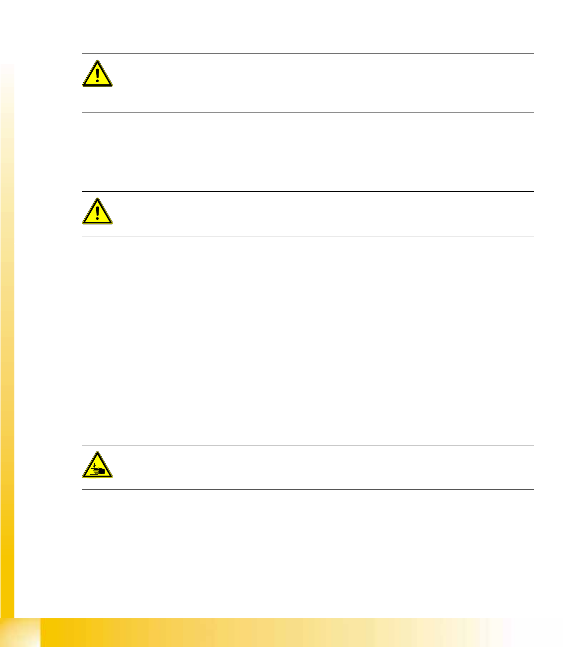
X Swing both handles up (1).
ATTENTION: OPERATIONAL SAFETY
Make sure that all component trolleys are docked onto the machine before you operate the
machine. If this is not the case, the machine will remain in emergency stop mode and the
placement process will be interrupted.
CAUTION:
Unused locations need to be occupied with dummy feeders, to ensure that the machine is
protected against unauthorized access.
DANGER:
When raising the changeover table plate, never reach into the gap between the feeder modules
and the empty tape duct.
Component Handling
Docking and Undocking the Changeover Table Overview
Student Guide Advanced Level 1 SIPLACE D-Series
EN 05/2007 Component Handling
8-5
8-2: Component trolley - swinging up the handles for pushing the trolley
Legend
X Use both hands to pull the component trolley out of the machine by the handles.
X Press the button to lower the changeover table (2). This ensures that the component trolley does not
tip over so easily, when outside the machine.
Docking the component trolley
X Check whether the contact surface for the changeover table plate is clean.
X Carefully push the component trolley near to the machine.
X Plug the component trolley connection cable into the machine.
X Open the cover flap over the pushbutton for lifting the changeover table.
X If the "lower table only with connected compressed air supply" option is installed at the changeover
table, raise the table.
X Press the pneumatic button on the machine frame until the changeover table plate has reached its
top position.
X Carefully push the component trolley into the machine, as far as the end stopper.
X Check whether the centering holes in the changeover table plate are positioned exactly over the
centering bolts of the machine.
X Press the button to lower the changeover table plate.
1 Handle 2 Switch for lowering the changeover table
NOTE:
Shorten the tapes at the front end of the S feeder modules to around 3 cm, before you dock the
component trolley.
CAUTION:
Check whether the placement head is outside the component trolley travel range.
DANGER:
When lowering the changeover table plate, never reach into the gap between the feeder
modules and the empty tape duct.
Component Handling
Overview Docking and Undocking the Changeover Table
Student Guide Advanced Level 1 SIPLACE D-Series
Component Handling EN 05/2007
8-6
X Make sure that the centering bolts engage with the centering holes in the changeover table plate and
that the changeover table plate has been fully lowered.
X Close the cover flap on the pushbutton.
X Close the protective hood.
X Press the START button to start the machine.
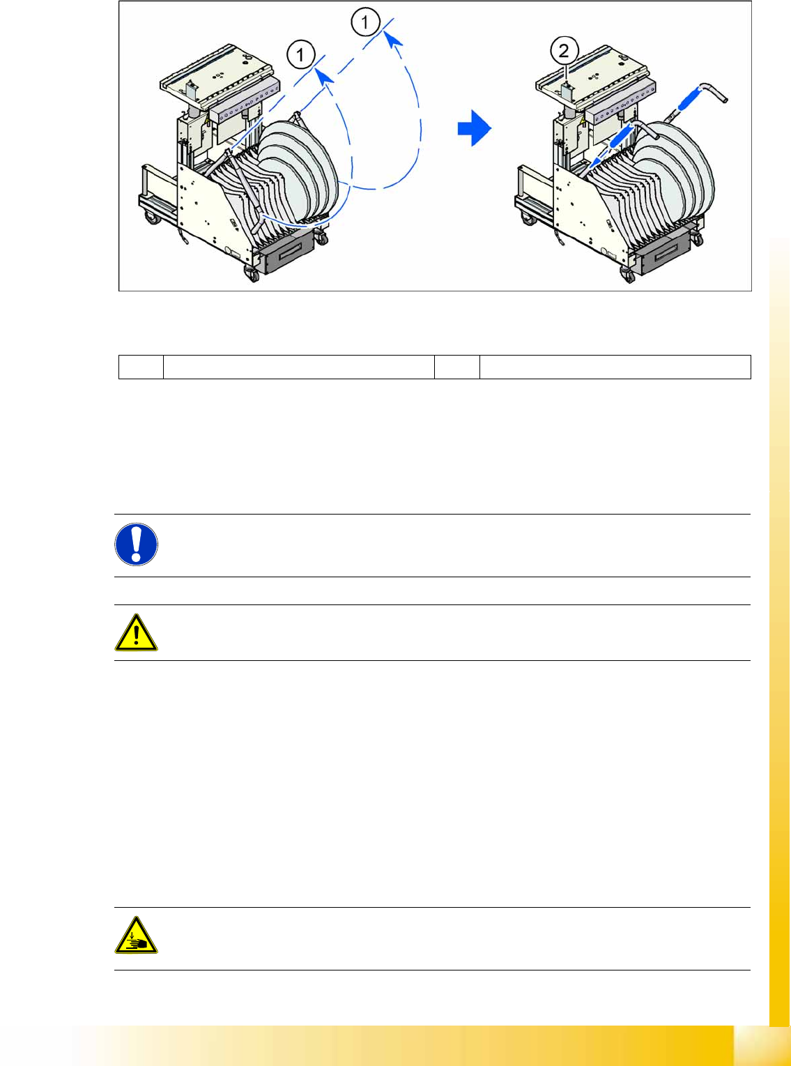
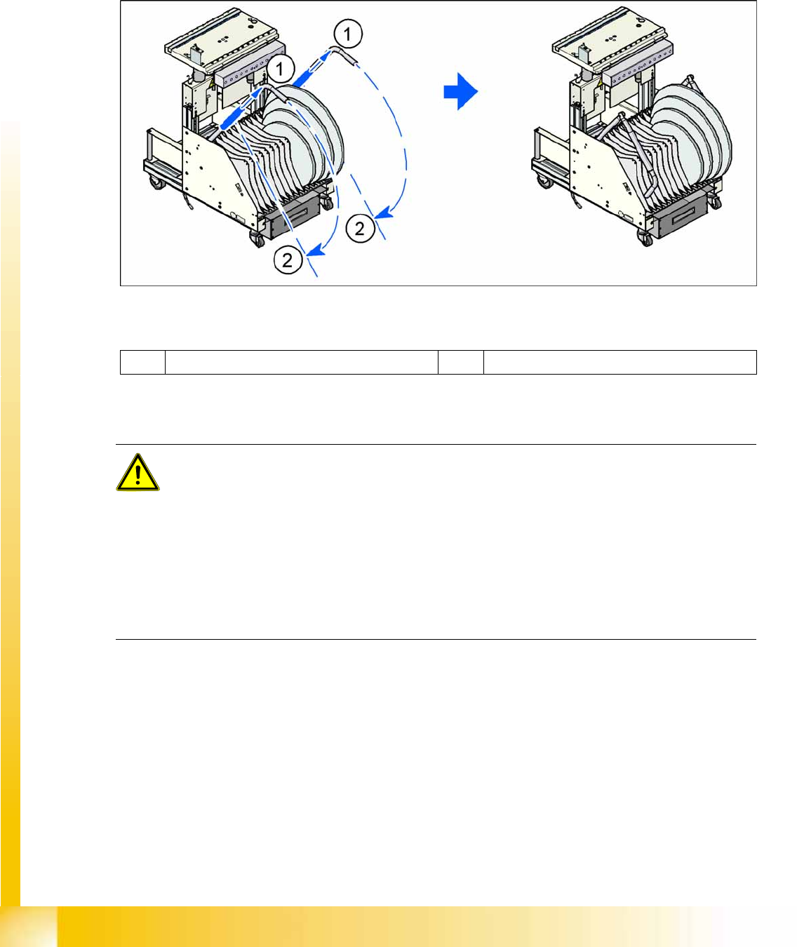
X Pull the tube (1) upwards at both handles and then swing the handles down (2).
8-3: Component trolley - swinging down the handles for pushing the trolley
Legend
Safety Instructions for Moving the Component Trolley
1 Pulling the tube upwards 2 Swinging the handles down
WARNING:
To prevent accidents, ALWAYS follow the rules listed below when you move the component
trolley.
X Always hold the handles with both hands when you want to move the component trolley.
X Remember that a component trolley with the full complement of feeder modules can tip over
sideways or forwards on gradients of 20 or more.
X Make sure that the surface on which the trolley is moved has a significantly smaller gradient.
X Be careful not to collide with obstacles. The trolley could tip forward if it is traveling fast
enough.
X Before the component trolley is moved, make sure that it has been lowered.