D-serie level 1 EN.pdf - 第43页
Overview Changeover Table Components Assemblies S tude nt Guide Advanced Level 1 SIPLACE D-Series EN 05/2007 Overview 3-19 3.4.6 Changeover T able Compo nent s 3.4.6.1 Setting the Height of the Ch angeover T able The cha…
Overview
Assemblies Power Supply Unit
Student Guide Advanced Level 1 SIPLACE D-Series
Overview EN 05/2007
3-18
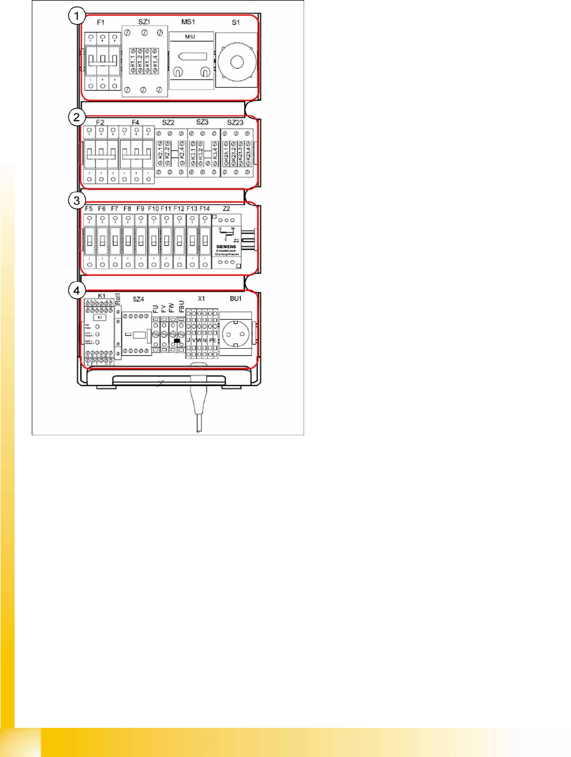
3-12: Power supply (front view)
Legend
1. F1: 3x 230 V AC
SZ1: main contactor
MS1: Motor protection switch
S1: main switch
2. F2: 220 V AC for 5 V power supply
F4: 3x 140 VAC X/Y axes
SZ2,SZ3, SZ23: auxiliary contactors U,V,W for
X/Y servos
3. F5: 150 V DC star axis servo
F6: 40 V DC Z/DP axis servo
F7: 40 V DC changeover table
F8: 40 V DC PCB handling (conveyor)
F9: 8 V DC changeover table (only in D4, due
to 4 changeover tables)
F10: 48 V DC Vision illumination
F11: 24 V DC terminal strip distributor 2/4
F12: 24 V DC Microbox PC (MC)/control "ON"
(K1)
F13: 24 V DC Box PC (SR)/axis unit 1/2
F14: 24 V DC conveyor control (TSP 301)/
monitors
Z2: discharge inductor
4. K1: protective contactor combination
Relay1: control ON - button
SZ4: control ON - software
FU: fuse 6.3 AT 220 VAC to GND
FV: fuse 6.3 AT 220 VAC to GND
FW: fuse 6.3 AT 220 VAC to GND
FBU: fuse 6.3 AT 220 VAC to GND
X1: feed in - terminal strip
BU1: service socket
Overview
Changeover Table Components Assemblies
Student Guide Advanced Level 1 SIPLACE D-Series
EN 05/2007 Overview
3-19
3.4.6 Changeover Table Components
3.4.6.1 Setting the Height of the Changeover Table
The changeover table can be manually set to the following PCB transport heights
830 mm PCB transport height
900 mm PCB transport height
930 mm PCB transport height
950 mm PCB transport height
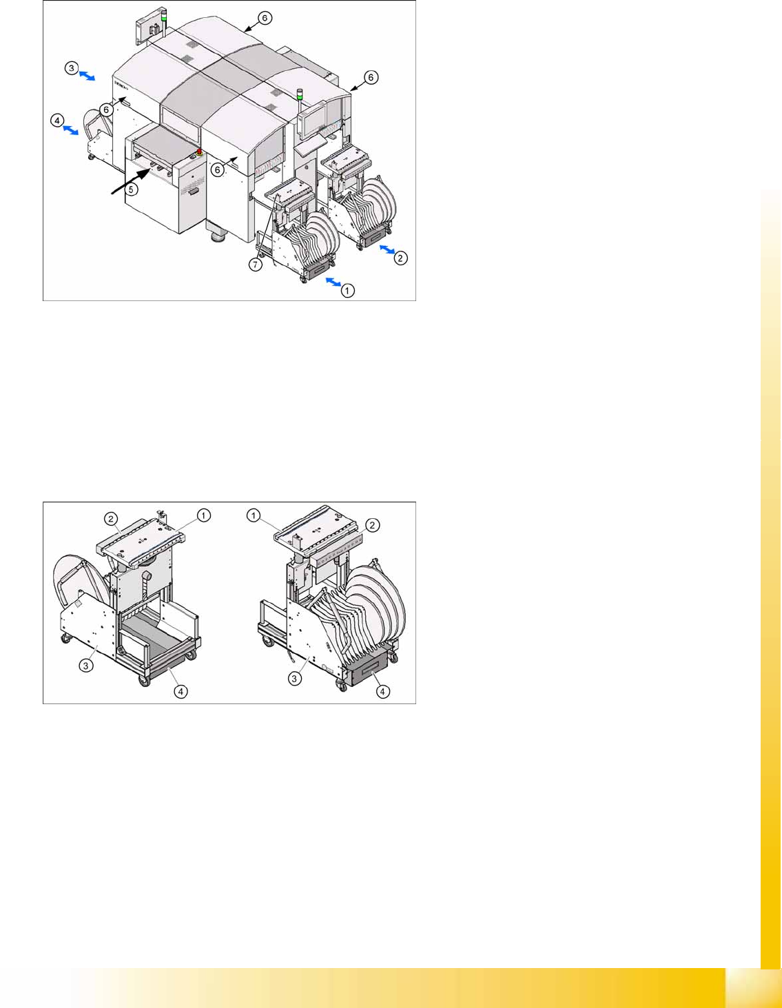
3-13: Button for docking and undocking changeover tables (D4)
Legend
1. Changeover table location 1
2. Changeover table location 2
3. Changeover table location 3
4. Changeover table location 4
5. Transport direction
6. The button for docking and undocking the
changeover tables is located under the feeder
cover flap of each changeover table
7. Switch to lower the table after undocking/
docking
3-14: Changeover table (D4 shown as example)
Legend
1. Feeder table plate
2. Communication unit
3. Tape container
4. Waste container for tape cuttings
Overview
Assemblies Changeover Table Components
Student Guide Advanced Level 1 SIPLACE D-Series
Overview EN 05/2007
3-20
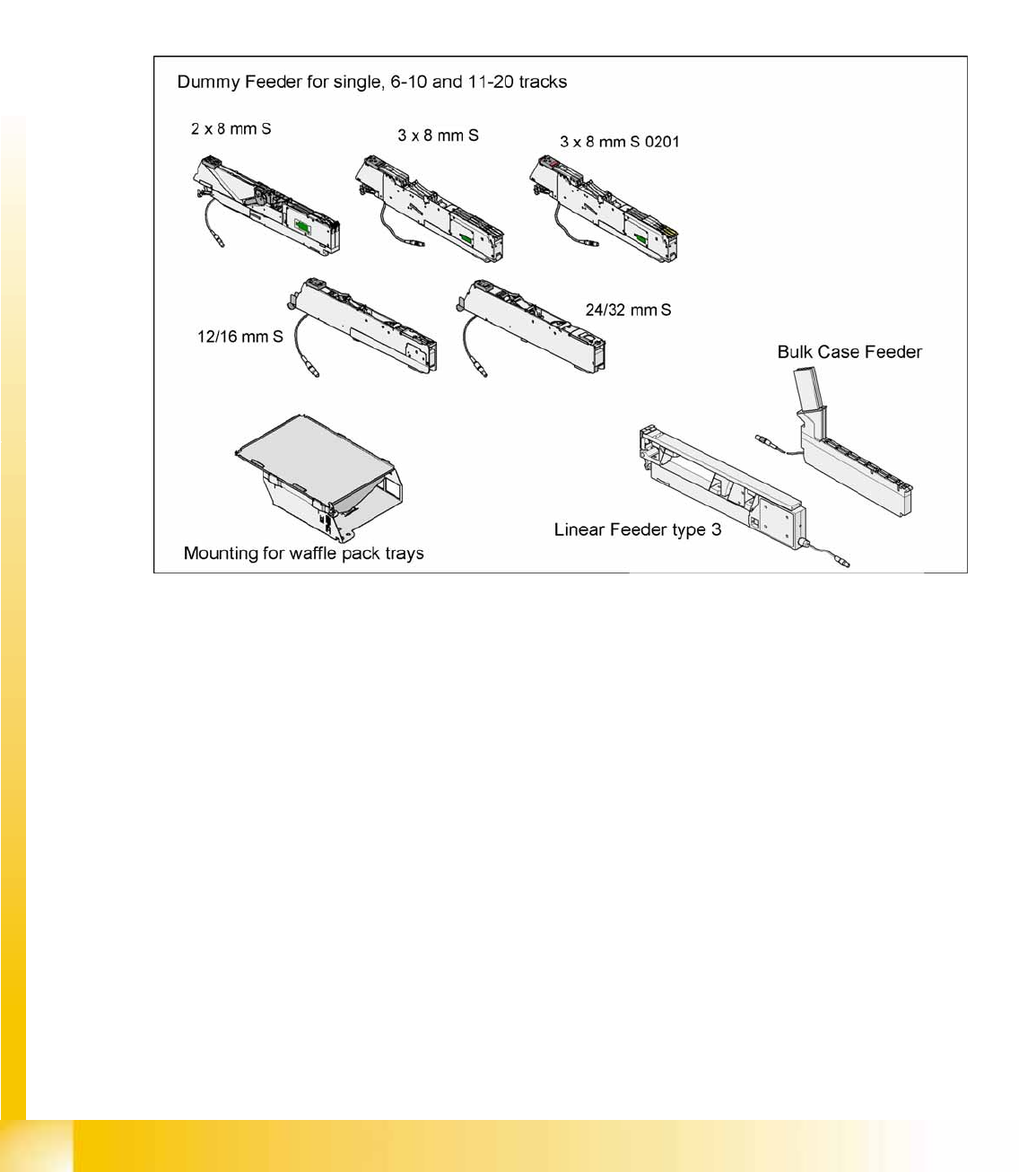
3.4.6.2 Overview of S-Feeder
Description: 9 different feeders are enough to process tapes with widths from 8 to 88 mm. The tape reels
on the feeder are taken up by the component trolley tape container. The cutter then cuts up the empty
tape automatically. SIPLACE feeders are known for their short cycle times and highly accurate pickup
positions.
These feeders can also be used in other SIPLACE placement machines.
In addition to the tape feeders, bulkcase feeders, linear feeders, surftape feeders, Dipflux modules,
component reject conveyors and manual trays can also be used. If a location is not occupied, a so-called
dummy feeder is inserted for safety purposes.
3-15: Overview of standard feeders