D-serie level 1 EN.pdf - 第169页
SIPLACE Vision Fiducial Shapes For PCB Position and Placement Position Recognition Op tical Fiducial Models S tude nt Guide Advanced Level 1 SIPLACE D-Series EN 05/2007 SIPLACE V i sion 10-3 The maximum size of the fiduc…
SIPLACE Vision
Optical Fiducial Models Fiducial Shapes For PCB Position and Placement Position Recognition
Student Guide Advanced Level 1 SIPLACE D-Series
SIPLACE Vision EN 05/2007
10-2
10.1.1.1 Illumination Type for Fiducials with Standard Camera SST38
The following recommendations apply for the choice of fiducial material:
When teaching the fiducial shapes, the complete programmed PCB is defined, including all fiducial
coordinates! At the station, Single Functions is selected to move the first PCB into position for teaching
the fiducials and inkspots. All required fiducials are taught and can then be tested with all cameras, using
the Test all fiducials function. Production then starts with the next PCB.
10.1.1.2 Fiducial Arrangement on the PCB
If the fiducials are only arranged in one row on the PCB, this enables you to determine the PCB position
and the PCB angle.Since two fiducials are sufficient for this, SIPLACE Pro only transmits two fiducial
positions.
The PCB fiducial positions transmitted to the station;
The following can be calculated: PCB position, PCB angle and PCB length offset.
The PCB fiducial positions transmitted to the station;
The following can be calculated: PCB position, PCB angle plus PCB length and width offset.
10.1.1.3 Importing Fiducials
All fiducials which are defined as such in ICOS need to be retaught for SIPLACE Vision.
In this case, there is no need to consider a mutual influencing of the two optical recognition systems, as
sensor-specific saving of the parameters is possible (5 SST, 24 SST,…).
Special case: SIPLACE Vision accepts double crosses as a synthetic fiducial type; ICOS systems define
this type as 2D pattern; it is therefore not possible to import this fiducial type.
10.1.2 Fiducial Shapes For PCB Position and Placement Position Recognition
The following 7 (or 9) fiducial shapes can be taught as synthetic fiducials:
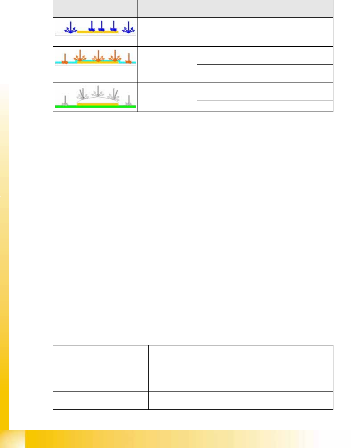
Example Illumination type/
illumination color
PCB material
e.g. gold on ceramic
Blue for recognition of gold or silver-colored fiducials on
white material (ceramic).
Red, diffuse to penetrate the coating on matt fiducial surfaces, so
that the PCB fiducial can be recognized.
for recognition of matt fiducials on any PCB surface
and any PCB material.
Red, steep combined
with diffuse
for recognition of fiducials under the coating of
reflective fiducial surfaces (e.g. glass plates).
For reliable recognition of reflective fiducial surfaces.
Fiducial type
(name in fiducial list)
Minimum size To be taught/comments
Cross; Double cross; 0.3 mm long,
0.1 mm thick
Shape, dimensions and line thickness; can be shown as
light or dark
Circle D 0,25 Shape, dimensions; can be shown as light or dark
Circular ring D 0.3 mm,
0.1 mm thick
Shape, dimensions and line thickness; can be shown as
light or dark
SIPLACE Vision
Fiducial Shapes For PCB Position and Placement Position Recognition Optical Fiducial Models
Student Guide Advanced Level 1 SIPLACE D-Series
EN 05/2007 SIPLACE Vision
10-3
The maximum size of the fiducial is generally 3 mm and the maximum line thickness for cross 1.5 mm,
for double cross 1.2 mm. The minimum possible tolerance is 2%, the maximum possible tolerance is
20% of the nominal size.
The fiducials now only contain the data required for optical recognition. The size of the search field and
the fiducial application are assigned to the fiducial coordinates.
The following measurement results are issued for the structure found:
Rectangle or square
(square is a special type of rectangle)
0.25 mm long/
wide
Shape, dimensions; can be shown as light or dark
The square is a special type of rectangle in which both
sides are to be set identically.
Rectangle frame / square ring (square
ring is a special type of rectangle
frame)
0.3 mm long,
0.1 mm thick
Shape, dimensions and line thickness; can be shown as
light or dark
The square ring is a special type of rectangular ring in
which both sides are to be set identically.
Diamond – a square rotated by 45° 0.35 mm long/
wide
Shape, dimensions; can be shown as light or dark
Patterns of other 2D fiducial shapes
(triangle, quarter circle segment, PCB
circuit structure etc.)
0.3 mm long,
0.1 mm thick
Pattern recognition algorithm, the fiducial is marked as 2
D fiducial in the fiducial list.
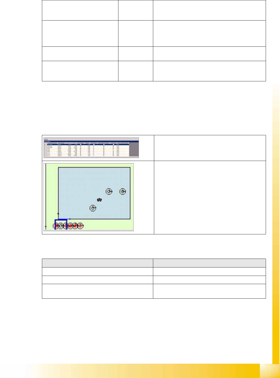
Fig. Programming field Fiducials
Fig. PCB section
When teaching the fiducial: When centering the fiducial:
=> X position of structure to camera center point => X position of structure to camera center point
=> Y position of structure to camera center point => Y position of structure to camera center point
=> Angle deviation of structure to PCB camera
coordinate system
SIPLACE Vision
Optical Fiducial Models Fiducial Shapes For PCB Position and Placement Position Recognition
Student Guide Advanced Level 1 SIPLACE D-Series
SIPLACE Vision EN 05/2007
10-4
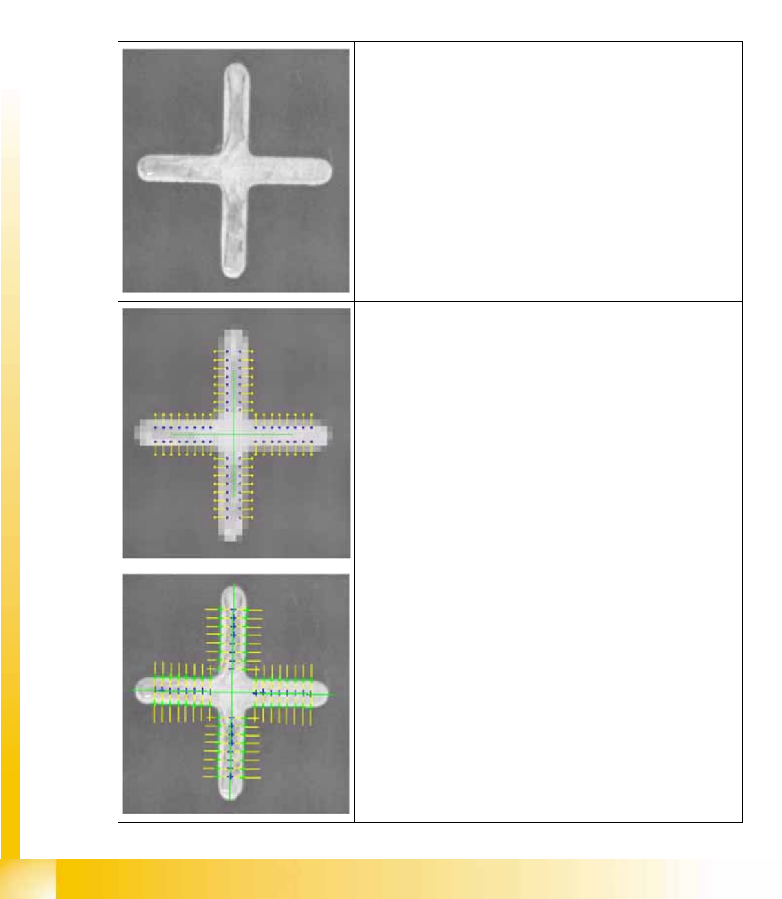
10.1.2.1 Synthetic Fiducials
In a rough step with reduced resolution, the gray value difference between two points is determined
for multiple pairs of points. The position of these points is calculated using the geometric model. The
gray value differences are then used to determine a position.
In a fine step, the highest gray value difference in each case is measured along the scan lines.These
positions are used to calculate regression lines for determining the fiducial positions.The positions
of the scan lines are determined using the positions of the pairs of points from the rough step. Parallel
to position determination, a quality value is calculated, which indicates how well the image and model
match one another at the positions found.
Fiducial camera image
Rough search with reduced resolution:
Pairs of points are yellow/blue.
The blue point has a higher gray value than the yellow point.
Fine search:
Position of scan lines (yellow) for the pairs of points found.
Green cross: positions found for the highest gray value gradients
along the scan line.
Green lines: regression lines.