D-serie level 1 EN.pdf - 第55页
Overview SIPLACE Vision Assemblies S tude nt Guide Advanced Level 1 SIPLACE D-Series EN 05/2007 Overview 3-31 3.4.9.5 Component Camera (S tandard T ype 36, Option T ype 33) T echnical Dat a 3-25: Component camera for Twi…
Overview
Assemblies SIPLACE Vision
Student Guide Advanced Level 1 SIPLACE D-Series
Overview EN 05/2007
3-30
Technical Data
3.4.9.4 Component Camera C&P12 (Optional, Type 29)
Technical Data
Component
dimensions
0.5 x 0.5 mm
2
to 18.7 x 18.7 mm
2
Component range 0402 to PLCC44 incl. BGA, µBGA, flip-chip, TSOP, QFP, SO to SO32, DRAM
Min. lead pitch 0.5 mm
Min. ball pitch 0.45 mm
Min. ball diameter 0.25 mm
Field of view 24.5 x 24.5 mm2
Method of
illumination
Front lighting (6 programmable options on 4 levels )
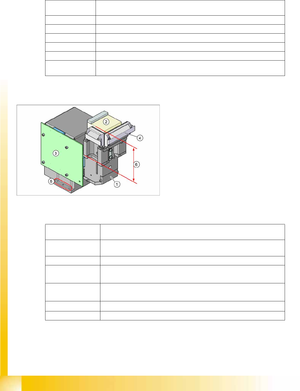
Technical data for camera type 28
3-24: Component camera as default on the C&P12 head
Legend
1. Component camera optics and illumination
2. Camera amplifier
3. Illumination control
4. Flat ribbon cable holder for C&P head leads
5. Camera fixtures
2 x fixture drillings and 1 x centering drilling
each on both sides
6. The high construction helps you to
differentiate camera type 29 from camera type
28.
Component
dimensions
0.3 x 0.3 mm
2
to 27 x 27 mm
2
Component range
0201 to 27 x 27 mm
2
PLCC, SO, QFP, TSDP, SOT, MELF, CHIP, IC, BGA
Min. lead pitch 0.3 mm
Min. ball pitch
0.25 mm for component < 18 x 18 mm
2
0.35 mm for component ≥ 18 x 18 mm
2
Min. ball diameter
0.14 mm for component < 18 x 18 mm
2
0.2 mm for component ≥ 18 x 18 mm
2
Field of view
31 x 31 mm
2
Method of illumination Front lighting (6 programmable options on 4 levels )
Technical data for camera type 29
Overview
SIPLACE Vision Assemblies
Student Guide Advanced Level 1 SIPLACE D-Series
EN 05/2007 Overview
3-31
3.4.9.5 Component Camera (Standard Type 36, Option Type 33)
Technical Data
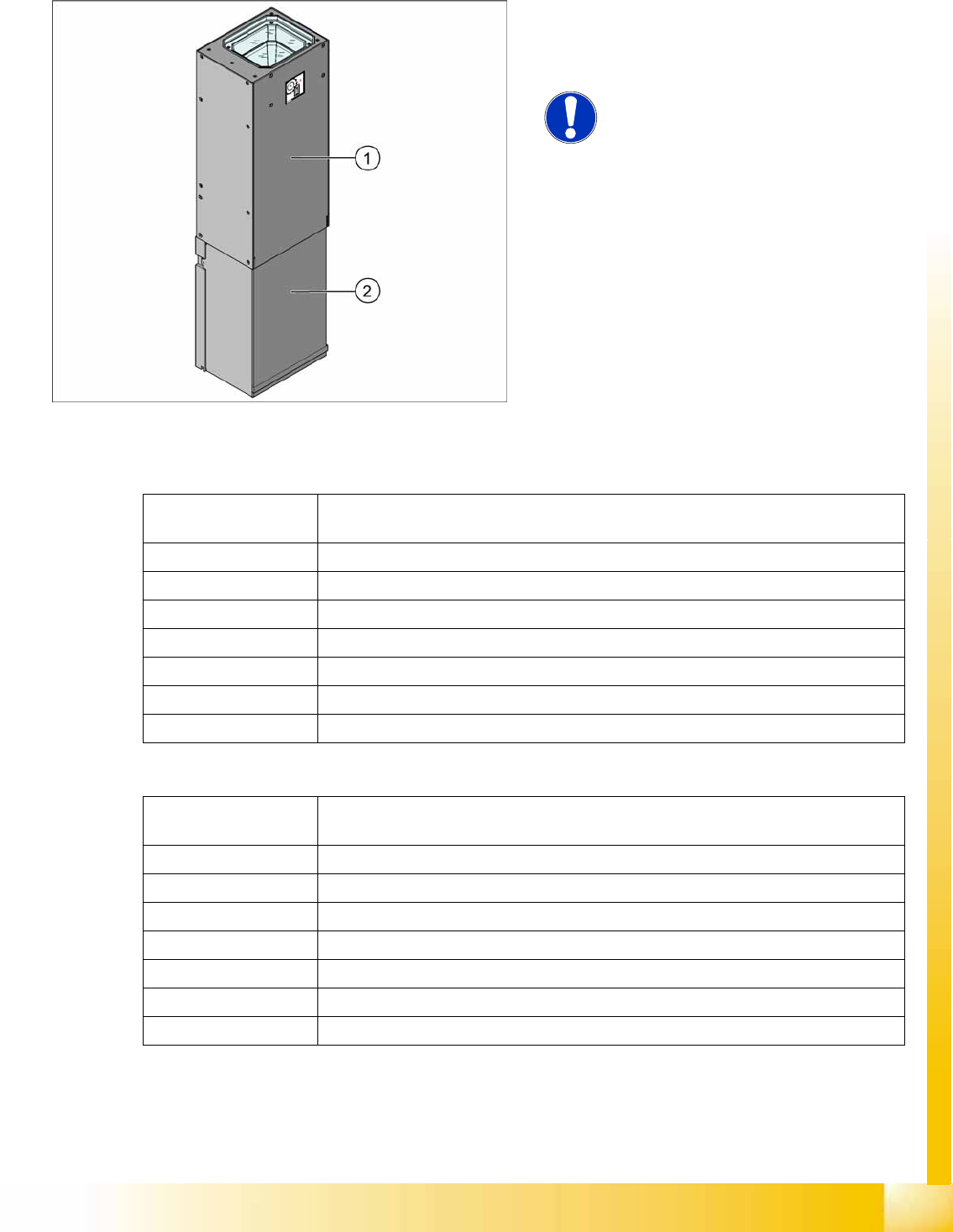
3-25: Component camera for Twin head (D3) or P&P module (D1)
Legend
1. Top section with camera lens system
2. Lower camera cover
NOTE:
The standard camera (type 36) and the
optional camera (type 33) can be
recognized by their labels.
Component
dimensions
0.8 x 0.8 mm² to 32 x 32 mm² (simple measurement)
Component range 0603, MELF, SO, PLCC, QFP, electrolytic capacitors, BGA
Min. lead pitch 0.4 mm
Min. lead width 0.24 mm
Min. ball pitch 0.56 mm
Min. ball diameter 0.32 mm
Field of view 38 x 38 mm²
Method of illumination Front lighting (6 programmable options on 4 levels )
Technical data for camera type 36
Component
dimensions
0.8 x 0.8 mm² to 55 x 45 mm² (simple measurement)
Component range 0603, MELF, SO, PLCC, QFP, electrolytic capacitors, BGA
Min. lead pitch 0.3 mm
Min. lead width 0.15 mm
Min. ball pitch 0.45 mm
Min. ball diameter 0.25 mm
Field of view 65 x 50 mm² simple measurement
Method of illumination Front lighting (6 programmable options on 4 levels )
Technical data for camera type 33

Overview
Assemblies Conveyor System
Student Guide Advanced Level 1 SIPLACE D-Series
Overview EN 05/2007
3-32
3.4.10 Conveyor System
3.4.10.1 General
The standard machine is equipped with a single PCB conveyor. A dual PCB conveyor system is
optionally available. Depending on individual requirements, either the left or right conveyor side can be
selected as the fixed conveyor side.
In the Processing Area (PA1 or PA2), the PCB board will be clamped from the bottom side against the
fixed holder on the conveyor system. Therefore, the space between the upper side of the board and the
placement head remains the same for each board and no longer depends on the thickness of the board.
This means that the placement performance also no longer depends on the board thickness. The PCB
fiducial centering can also be optimized. The consistent space between the board upper edge and the
PCB camera means that the PCB camera is always optimally focussed on the upper side of the board.
The PCB fiducial shape is optimally imaged on the CCD chip of the PCB camera.
The PCB transport in the SIPLACE machine is configured so that the C&P12 head can place
components up to a maximum height of 6 mm.
The machine height can be adjusted so that the machine can also be integrated into lines with transport
heights of 830, 900, 930 or 950 mm. Communication between the PCB conveyors of the different
machines is provided with the help of a SMEMA or SIEMENS (optional) interface (D-series). Standard
interface: SIEMENS).
The transportation of the boards is monitored and controlled by light barriers, consisting of a transmitter
and a receiver module. Once the board has reached the placement area and the board has been
recognized by the light barrier, the speed of the conveyor belt is reduced. The board is stopped with the
help of a laser beam and is then clamped into place from below.
Terminals
The PCB is lifted for placement of components and pressed up against the PCB clamping rail. When the
lifting table rises the PCB and the complete conveyor drive unit is lifted up to the clamping position. This
method enables the placement surface to remain in the same position, irrespective of the board
thickness.
Boards with a length up to 368 mm (D1/D2: 400 mm) are clamped into place in the relevant placement
area. Clamping does not take place on the input and output conveyor. However, boards with lengths
above 368 mm are placed up to a length of 610 mm on the conveyor belt and are only supported by the
lifting table in the placement area.
Width adjustment
The width is adjusted by means of a motor as programmed. For dual conveyor systems, differing widths
can be set for the two conveyor belts. The width adjustment uses a stepping motor, meaning that the
new PCB width can be set independently of other machine components (e.g. the Y-gantry). The
proximity switch on the conveyor side is no longer needed.
The PCB width is adjusted via two adjustment units (pneumatic cylinder), which are installed under the
input and output conveyors. The stepping motor moves the two adjustment units synchronously back
and forth, through the use of ball bearing spindles and a toothed belt.